81 Mark IIB Bias Pot Info Needed...Pics Inside

The Boogie Board

Help Support The Boogie Board:

This site may earn a commission from merchant affiliate links, including eBay, Amazon, and others.

davec69

Well-known member
Joined
Feb 15, 2007
Messages
48
Reaction score
0
Location
S. SF, CA
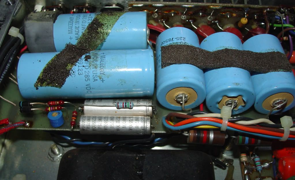
I want to do the cermet bias trimpot mod to my IIB, but I'm confused as to which 10k resistor is the correct one. I'm pretty sure that I have the correct area, but there are 2 - 10k resistors in close proximity. Can someone tell me which arrow in the photo below is the correct resistor that I need to replace with the cermet trim? The plan is to remove it and put in a 50k cermet pot. The resistors in question are beneath the 2 which are bridging them.

Another question. I want to put a safety resistor in series with the cermet pot, but I couldn't find a definitive value for the IIB. Someone suggested 2.9k in another thread. Does that sound correct for the IIB?

FYI. Before mod readings with the installed STR440's were in the 30ma range, except for one tube which is reading 25.8ma. I stuck in a set of Tung Sol 6L6GC and got readings of 15-16ma for all tubes with the stock 10k resistor. The STR's were a little cold, but the Tung Sol's are artic. I need the adjust pot.

iibbias.jpg
 
On the MK IIA the place where the 6.8K resistor is had a 10K trim pot. The schematics look similar, but the orientation is a bit
different. The circuit is also tweaked for 60W, 100W and GEQ's so there can be a few different appearances. Also, be sure that
when your in there, you are working on the bias circuit and not the negative GEQ supply.

DSC01745-1.jpg
 
Thanks for the response. I think the MKIIA's came stock with the trimpot. They were removed in the MKIIB's.

I just finished adding the trimpot to my MKIIB. Took me a couple hours, because I dropped my first attempt at the pcb, and rolled over it with my chair while trying to find it on the floor. Hate i when that happens.

I took an initial bias reading before starting. I was getting 30ma on the installed STR440 6L6 tubes. The Tung Sol's that I wanted to use, only got up to 15ma or so.

1. My MKIIB is rackmount, so opening it was just a matter of removing the 4 screws in the top. Unplugged from the power outlet before starting.

2. I then used my homemade Capacitor discharger (alligator clip to chassis > 5W 2K Resistor > old multimeter probe) to drain the caps, so I could live to write this. Checked the voltage before draining, only 10v present. After draining, they were all in the millivolt range. I watched the meter as they slowly climbed back up after removing the discharge tool. They made it all the way back up to 9v in a fairly short time, even with the amp unplugged, So I clipped the discharge tool to one of the caps and left it there while I worked.

3. Grabbed a 50K / 5w trimpot from my box o goodies, and a 2.9k / 1/2w resistor. (read in another thread that this would work). Make sure not to use a 1/4w resistor here. That's what most of us have lying around.

4. I used some needle nose pliers to squeeze legs 1 and 2 together into on leg.

bias1.jpg


5. Grabbed a piece of veroboard to make the PCB, to mount the trimpot and resistor. You don't need it, but it looks prettier, and makes for a more stable mounting. Basically, everything is running in series. Black wire > Legs 1&2 trimpot > Leg 3 > either resistor leg > other side of resistor > Yellow wire

bias3.jpg


6. Put the Black and Yellow wires into my multimeter, to verify that it worked. It did. Since I am replacing a 10k resistor, I set this trimpot arrangement to read 10k across the yellow and black wires.

bias2.jpg


7. I wanted to use some standoffs from an old computer that I had, to mount the pcb to the chassis, but I couldn't find any that would work well, so I used a double sided tape mount from my goodies box, and a tiewrap.

bias4.jpg


8. Used some 409 cleaning spray to clean an area on the chasis , so the double sided tape would stick. Not sure how this arrangement will hold up to heat, though. We'll see.

bias5.jpg


9. Placed my little homemade pcb in the clean spot.

bias6.jpg


10. Carefully bent the two resistors bridging the one that I need to get to, out of the way so I could work, then clipped one end of the 10K resistor that I am replacing. Make sure to leave enough of the 10k resistor leg, to solder the wire to.

bias7.jpg


11. I then clipped the other side of the 10k resistor and removed it.

bias8.jpg


12. Finally, I soldered the yellow and black wires from my pcb, to the legs of the previous 10k resistor. Doesn't matter which wire you solder on which leg. This is not a plus and minus situation.

bias9.jpg


I then removed my discharge tool, and powered up. Took bias readings again, and thanks to me setting the trimpot to 10k previously, my bias readings after the install were almost exactly the same as before. 31ma this time.

I checked the trimpot, and sure enough, it was working. Bias was going up and down depending on which direction i moved the trimpot screw.

Next question was Do I have enough adjustment range in the trimpot, to get the Tung-Sols up to the 30-35ma bias range? I think this particular trim pot was 20 turn, which allows for finer adjustment than a 1 turn trimpot.

Sure enough, I was able to get the Tung-Sol's up to 33ma, where I like them. I could have gone higher, but this is fine with me.

I Thought sharing this experience might be of value to anyone considering the bias mod in their MKIIb
 
In answer to my initial question.

The 10K resistor in the first photo which has the blue arrow pointing to it, is not the bias resistor. I repeat, is NOT the bias resistor. It's the green arrow.
 
Thanks for posting this.

Can you give us your opinion of what the difference in tone was from having the Tung Sols @ 15ma to 33ma, in regards to the clean and lead sounds?

I want to do something like this with my Mark III but I'm not sure exactly how to accomplish this with the Simul-Class differences in the 2 pairs of power tubes.
 
The original tubes were the Mesa Boogie 440 STR 6L6's running at 30ma.

Before the mod, I tried removing the STR's and putting in the Tung Sol's. The hope was that the Tung Sol's would fall in the same bias range, and nothing further would be required. When I measured the bias on the Tung Sol's, it was 15ma, I didn't even bother listening to them at that low of a reading.

Running the Tung Sol's this cold, was not an option. You get a soft spongy slightly distorted clean sound, and a little to no lead tone. I compare it to the dying battery sound in a distortion or fuzz pedal. If you want to hear the effect, plug your amp to a variac, and start lowering the voltage.

After doing the mod, I was able to bring the Tung Sol's up to 33ma. I much prefer these tubes to the STR-440's. They have a much more refined and cleaner, clean tone. The distortion sound gets similar treatment. They also make the bass range of this amp more usable.

The STR's are the perfect tubes, if you want that tried and true bass heavy Boogie tone. They are also bulletproof.

You might search the board here. I did see a post while I was looking, from someone who did this mod on their Simul-Class amp. Basically, you do the same thing, except you need to do it twice. Once for each set of tubes. When finished, each pair of tubes has it's own bias pcb as above.


kramerxxx said:
Thanks for posting this.

Can you give us your opinion of what the difference in tone was from having the Tung Sols @ 15ma to 33ma, in regards to the clean and lead sounds?

I want to do something like this with my Mark III but I'm not sure exactly how to accomplish this with the Simul-Class differences in the 2 pairs of power tubes.
 
FYI. Another option for the not so DIY'ers is here:

http://cgi.ebay.com/ws/eBayISAPI.dll?ViewItem&item=320510207372&ssPageName=STRK:MEWAX:IT
 
Not intended to be a thread jack, but anybody try the bias mod on a Simul-Class Mark II (A/B/C)? Obviously, the bias on the Class A sockets really isn't in the Class A range, at around 35mA. I heard somewhere that they should be brought up to 42mA to be true Class A. Obviously, to keep things balanced with the AB sockets in the middle, grid resistor swaps would be required, and since there is a voltage divider circuit at G1 at each of the outer sockets, a bit of thought is necessary there. I'd like to see the results, if anyone has done this.
 
THIS LOOKS LIKE A GREAT MOD TO DO...

i've got a 81 mk2b, 60w w/geq, no reverb.....

i've used boogie tubes since 1981.

at this point, i'd like to try something else, looks like the ticket.

i use an attenuator, and drive my amp hard (master on 6 typically)

so, where would i find a decent table of range of bias settings that will match to the different manufacturer's tubes, and where do i go to educate myself on where these ranges might fall within the 'boogie' sweet spot......?

sweet spot, of course, being a subjective opinion based on folks who have already done this type of mod, and have found a good midrange of settings with certain tubes?
 
A quick Google search turned up this page with general bias information:

http://www.svvintageamps.com/tubebias.php

Another good article on biasing at Aiken Amplification:

http://www.aikenamps.com/Why70percent.html

You may also want to read Mesa Boogie White Paper on biasing here:

http://www.mesaboogie.com/US/Smith/biasadjust.html

Generally, when I'm trying out a brand of tubes for the first time, I do a few Google searches and see what other people are suggesting.

Like you say, the so called "Sweet Spot" is really just personal preference. The safe bias range for a particular tube is fairly small. The sweet spot would be, the point within that range, that you prefer, for a particular amp. Only trial and error can tell you this.

If you get a little more technical, there's actually a point in the bias range where the tube performance and sound quality are at their peak. This is where Boogie sets the bias, with the resistor, I would imagine.


gonzo said:
so, where would i find a decent table of range of bias settings that will match to the different manufacturer's tubes, and where do i go to educate myself on where these ranges might fall within the 'boogie' sweet spot......?

sweet spot, of course, being a subjective opinion based on folks who have already done this type of mod, and have found a good midrange of settings with certain tubes?
 
>Photi G< said:
Not intended to be a thread jack, but anybody try the bias mod on a Simul-Class Mark II (A/B/C)? Obviously, the bias on the Class A sockets really isn't in the Class A range, at around 35mA. I heard somewhere that they should be brought up to 42mA to be true Class A. Obviously, to keep things balanced with the AB sockets in the middle, grid resistor swaps would be required, and since there is a voltage divider circuit at G1 at each of the outer sockets, a bit of thought is necessary there. I'd like to see the results, if anyone has done this.

I'm going to order some parts and try this on my Mark III Simul-Class. There are some other specificis on the Rectifier forum about this. I think if you bias the 6L6s for the inner power tubes up to around 30ma, the outter EL34s will be about 10-12ma higher. (*I'm guessing as I measured mine last night with new Mesa tubes and this outters were 26ma, inners were 15ma.)
 
davec69 said:
You may also want to read Mesa Boogie White Paper on biasing here:

http://www.mesaboogie.com/US/Smith/biasadjust.html

Generally, when I'm trying out a brand of tubes for the first time, I do a few Google searches and see what other people are suggesting.

Like you say, the so called "Sweet Spot" is really just personal preference. The safe bias range for a particular tube is fairly small. The sweet spot would be, the point within that range, that you prefer, for a particular amp. Only trial and error can tell you this.

If you get a little more technical, there's actually a point in the bias range where the tube performance and sound quality are at their peak. This is where Boogie sets the bias, with the resistor, I would imagine.

Every Mesa I've owned or currently own doesn't even get into 50% plate disapation when I've replaced my tubes with their 'Pre-tested' tubes. I have purchased tubes for my Mesa amp from reputable online dealers that said the tubes I bought were in the Mesa range that were. My thoughts on this is either my amp wasn't in spec to begin with or it has moved out of the tolerances that tube dealers are selling them to be in. In Randall Smith's article above he doesn't take that into consideration.
 
Back
Top