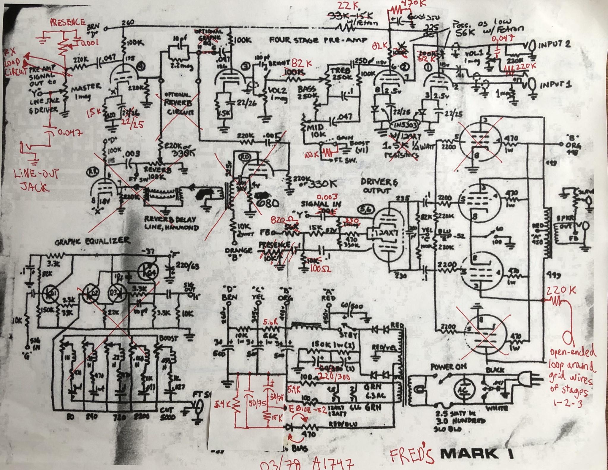
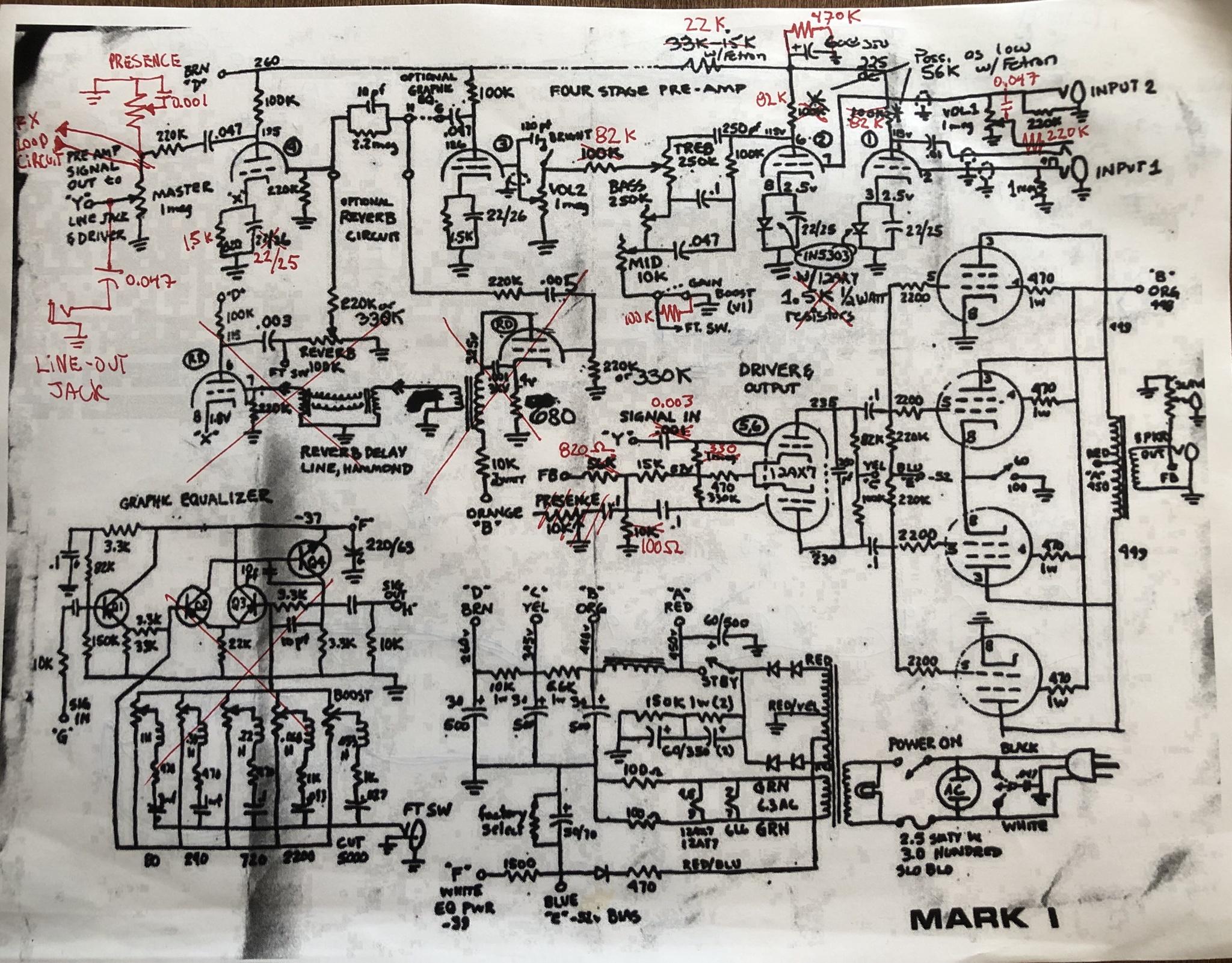
Ok so yesterday I spent some time tracing the preamp circuit (compared to the available drawings of the Mark I) and highlighted the differences.
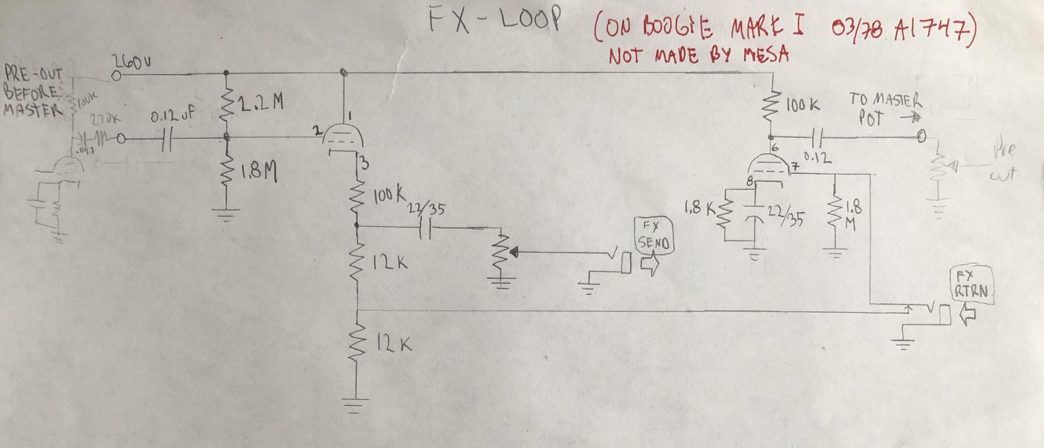
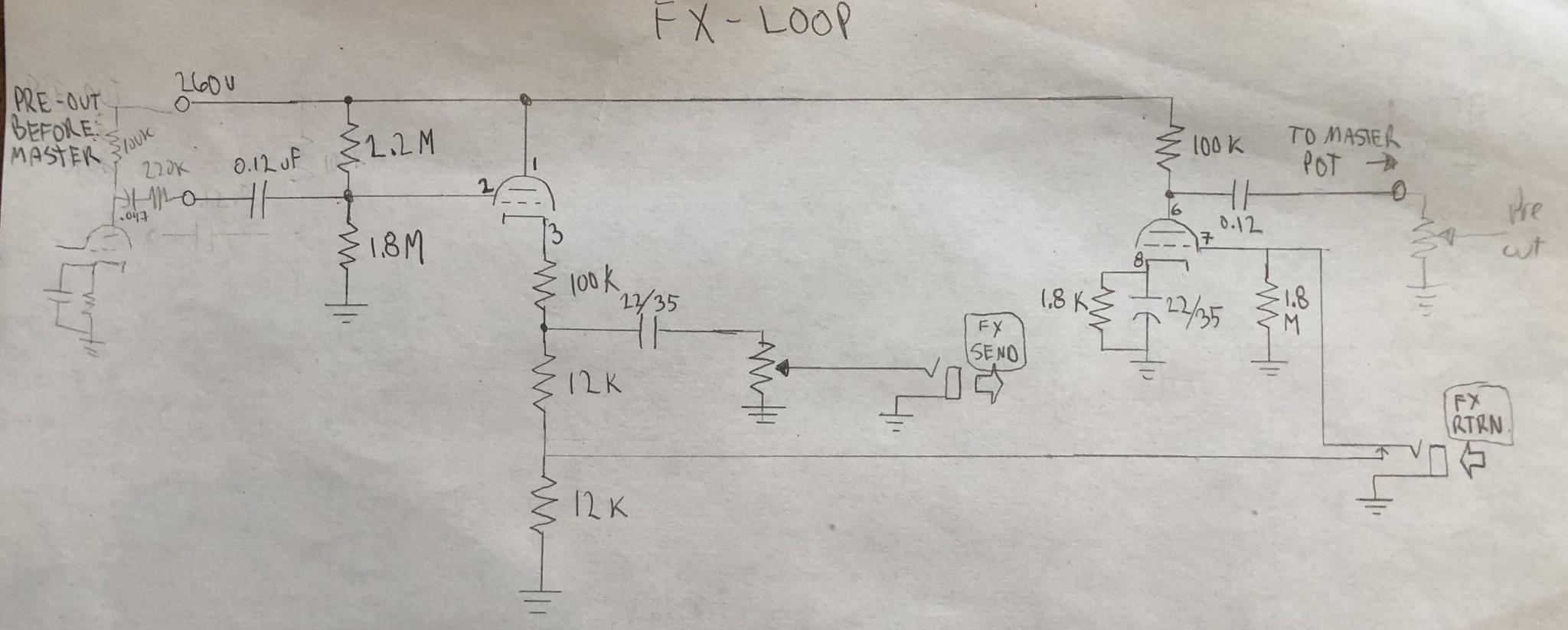
Also I traced my effect loop mod and researched the components a bit. The yellow caps are Philips Mepolesco series (sometime known as Philips chiclets) and are considered good vintage caps. The datasheet dates from 1974. I have not found when those caps stopped being made, but it seems like the FX loop mod was done a long time ago.
Here are pictures of my tracing, and below a list of things I'd like to figure out.
1) With the Fetron specific circuit, what is the point of having the 22k resistor above the two 82k load resistors, instead of having just the standard 100k load resistors? If converting for 12AX7, should'nt I remove the 22k, and end up with a standard supply and 100k load, along with the 1.5k cathode resistors? I don't necessarily plan on doing that, I mostly want to understand the impact of the current balance of the selected components.
2) Presence pot is not at the same location as in the schematic?
3) I will post later, but my bias circuit is quite different from the schematic.
4) Fx loop: your thoughts are welcome. I was surprised to see no load resistors at the plate, and all resistors at the cathode. Interestingly there is a voltage divider to send a fixed signal when nothing connected to the FX loop return.
5) The FX loop in indeed always in circuit, with both stages in use, but the pot is out of the circuit.
I started to review the power amp section and rectifier etc but not done yet, and that becomes harder with some wiring not visible under the boards. I was mostly interested to verify the pre amp and FX loop anyways.
I would be very interested to see pictures of an effect loop mod by Mesa to see how different they were doing it and maybe see some differences or similarities in components.
Fred
Fred,
Don’t get around much anymore or I would have piped in earlier…
Back in the day, Randy toyed with several PI/NFB presence circuits based on either a tweed bassman and Blackface Fender, which is not news of course. During the 70’s Mark 1 run either might show up in any given amp. Looks like you got the Blackface setup. Fixed NFB tuning that holds the output section together like a blackface Twin until you start peeling paint above 7-8, when the output section can’t keep up and you get that tasty output saturation, or the police shut you down, whichever comes first.
Your “presence” is not a presence control at all (it’s wise not to believe a knob’s label in any mark amp, at least before the mark IV). Trust but verify.
What you have is a treble gate that rolls of highs before the PI instead. You can find a couple of Mesa variations of this. The mark 1 Reissue schematic posted earlier shows one like yours. Sometime after Gil drew that one, Mesa added a small value bleed cap from the wiper to ground on subsequent Mark 1 Reissues. Mesa used the same “presence” solution on the heartbreaker and lone star (without and with the bleed cap respectively), but, they moved the circuit from in front of the master to post master. You can find those schematics online if you want a peek.
Obviously, you can play with those configurations to see what you like.
The FX loop story is much longer.
The loop in the reissue schematic is similar to a couple of other Mesa amps, however, quite different from the mark 2/3 series implementations.
The one in the reissue has an extra gain stage that is only active if you plug into the loop. If you run a straight cable from send to return, then the FX level controls the additional drive for that section’s gain. If you have an effect in the loop, you can set it for the effect input level. This controlled by some Jack-Switch trickery. No plugs in the loop equals total circuit bypass.
The Mark 2b was the first implementation of a loop in the Boogie. As mentioned previously, Randy implemented it as a cathode follower fo a low impedance output circuit. This “neutered” that stage of the mark 2A’s triode with effective unity gain… But it had some issues. Somewhere along the arc of the later Mark 2B, Mike came up with a fix—he converted that stage back to a gain stage and added a post loop volume, which can also serve as a master-master volume and the original master controlled the effects loop input.
This is a fix that was available by request, and Mike continued doing it after Mesa stopped. The other part of that package was moving the reverb from the classic topology to a spot inline with the loop.
This is known as the B+ or FX/Reverb mod in modern parlance. There is a lot of work to do it, as the function of two tube’s triode are electronically swapped and noise is a consideration. The result is more, and smother, gain structure, better interplay between rhythm and lead modes, the ability to crank and open up the preamp without shattering windows—for half-deaf geriatric players, virtually at bedroom levels. More total gain than a 2C, less than a C+. In fact, these are the architectural changes that Mike applied to the 2C that Randy had stuck with a low-Z implementation, albeit in a different location), which ultimately spawned the C+ and subsequent Mark architectures. (If you try the c+ FX loop test on a B+, it will behave like a +. )
These loops are serial and always active in the circuit whenever an effect is plugged in.
In the mark 1, a loop could be added to a non reverb amp by utilizing the space for the missing reverb tube. Mike did a number of these, but yours does not look like one to my eyes. But asking is the only definitive way to know about that. In a reverb amp, this would be a bit more surgery.
Hope that provided some context and clues—enjoy the journey!
Nice drawing BTW; something of a lost art.


")