nomad100hd
Well-known member
i think your confused, the caps don't raise the gain of the PI. just limites the frequencies that are being boosted. probably doesn't not affect dynamics either.


nomad100hd said:i think your confused, the caps don't raise the gain of the PI. just limites the frequencies that are being boosted. probably doesn't not affect dynamics either.
Koreth said:Conversely, the lower the frequency, the higher the cap's resistance, which in parallel with the plate resistor, presents a greater load to the plate, increasing the gain at lower frequencies. Thus, rather than simply cut everything above a certain point, The highs are cut, and the lows are boosted.
nomad100hd said:ok this is how it works.
The bigger the load the more gain. The max load the PI will see is 100K on one side, and 82k on the other. That is the max load any frequency will have on the PI. The caps lower the load for the higher frequencies, but can not present more of a a load for the lower frequencies. Key thing to notice is the plate resistors are in parallel with the caps. thus the resistors are limiting the total resistance any frequency can see.
[/quote]Koreth said:...the higher the cap's resistance, which in parallel with the plate resistor, presents a greater load to the plate, increasing the gain at lower frequencies. Thus, rather than simply cut everything above a certain point, The highs are cut, and the lows are boosted.


Koreth said:The crossover points you listed are the -3 dB points if the PI bypass caps were a lowpass filter. But placing the bypass cap in that position creates a shelving filter instead. The cap's resistance at high frequencies is much lower, acting as a low value resistor in parallel with the plate resistor, presenting the tube with less load resistance at high frequencies, reducing the gain at those frequencies. Conversely, the lower the frequency, the higher the cap's resistance, which in parallel with the plate resistor, presents a greater load to the plate, increasing the gain at lower frequencies. Thus, rather than simply cut everything above a certain point, The highs are cut, and the lows are boosted. This would by why some find the Nomad muddy. Cutting highs is one thing, but cutting highs while boosting lows is going to create a muddy sound. Try it on your favorite stereo sometime. Turn up the bass while turning down the highs. Going too far will make for a muddy sound.
Koreth said:Upon this we can agree. When I was using the terms greater and lesser speaking of the impedance at the plate, I meant relatively with regard to the highs and lows in relation to each other. I did not mean to imply that the bypass cap somehow made the plate resistors appear larger than their rated values.
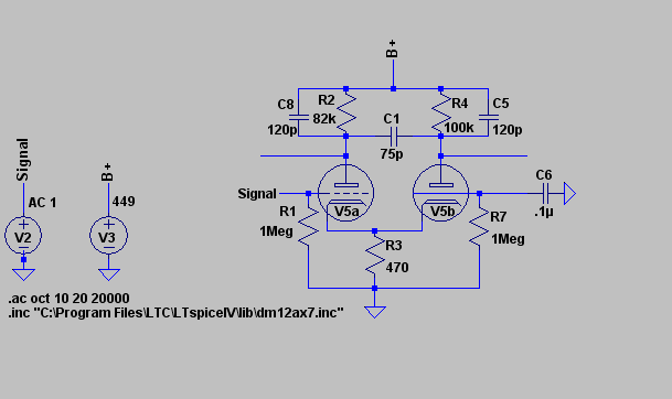
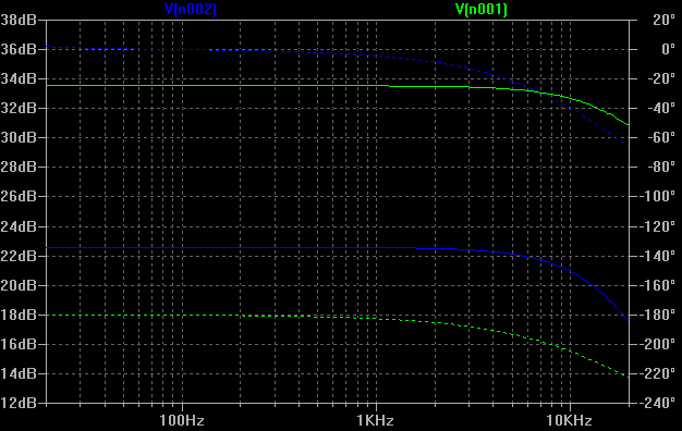
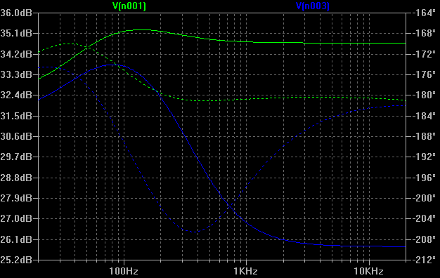
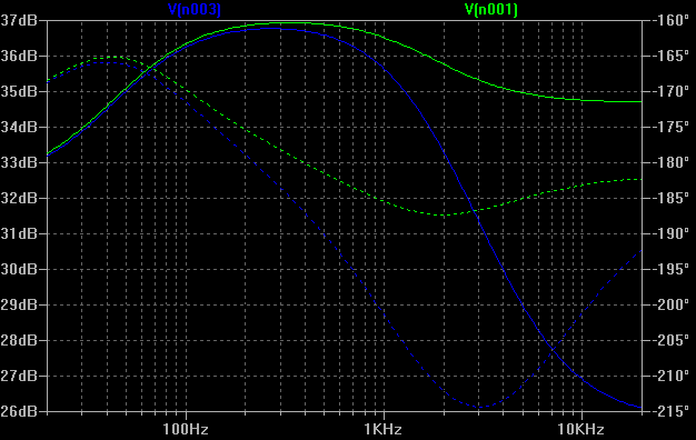
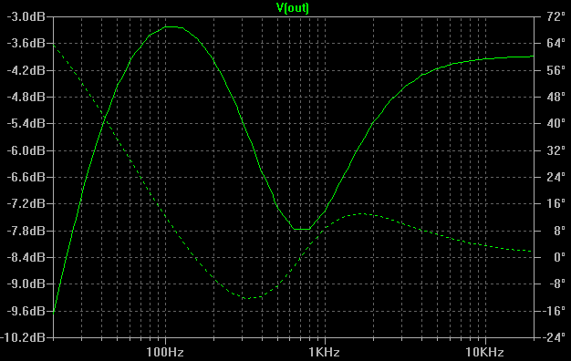
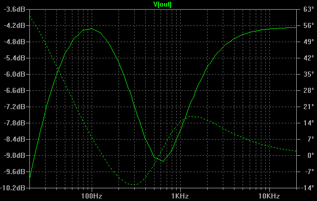
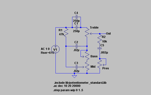
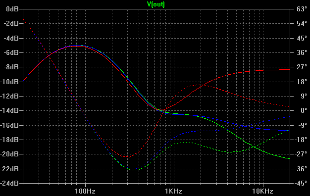
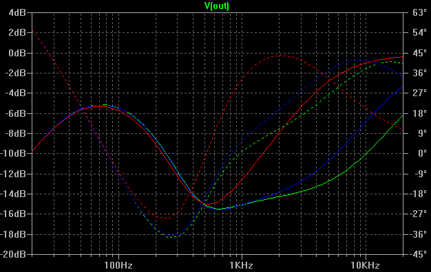
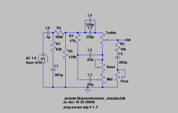
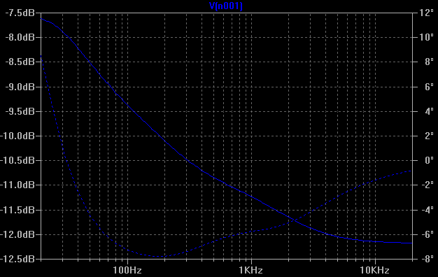
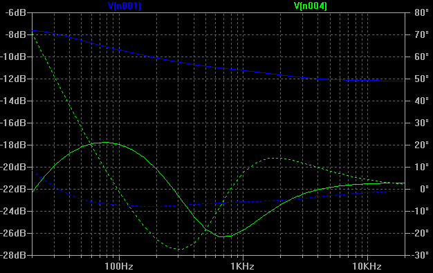
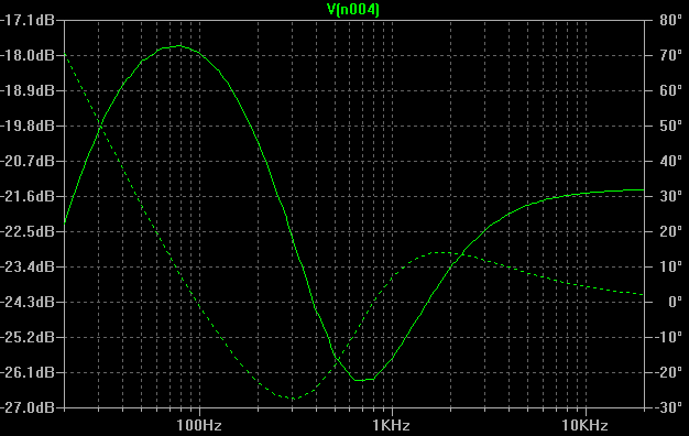
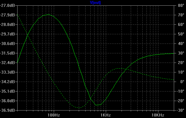
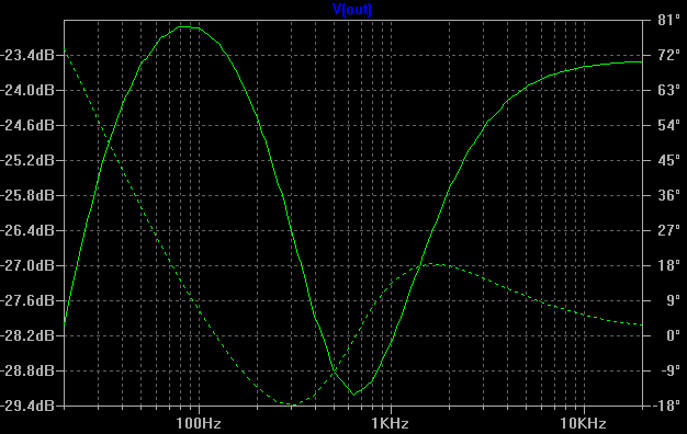
It has been a long time, but I have some new information as it relates to the de-mud mod. In the past couple months, I have figured out how to use one of the variants of SPICE, LTSpice for those of you who care. For those not in the know, SPICE is a general purpose analog electric circuit simulator. While it is very powerful and can be used to simulations to aid in the design of Integrated circuits and PC boards, it can also do simulations of vacuum tube amplifiers, since our amps are analog circuits. After finding some models for the 12AX7 tube, I was able to model various parts of the Nomad circuit and see their frequency response. In the process, I learned a few things that I want to share, which should allow us to make a much better, more effective de-mud mod that is as subtle or dramatic as we want.Koreth said:timowens said:I too struggle with the muddiness of my Nomad 55. Whenever I found this thread about the PI mod I was curious because a 120pF in parallel with a 100K crosses over at 13,263Hz and an 82K & 120pF at 16,174Hz. To me this would seem pretty much inaudible in a guitar amp so I figured they were to help prevent noise and oscillation but since I had to open my amp up anyway to work on one of the pots (don’t you hate the pots in the Nomad) I thought I’d try the mod. I took some pictures if anyone wants and I also recorded some before and after clips to see if I could really hear the difference. To me, it is real hard to hear the difference, on ch-3 with high-gain it is really hard but with ch-1 and ch-2 there might be a noticeable difference. I didn’t spend any time dialing in any tones and I didn’t spend any time adjusting the mic placement for the recording but for an A/B comparison the test should suffice. First I started off with ch-3, then I switched to ch-2 and ch-1 and back to ch-3. The only discrepancy would be when I backed off the volume on the guitar, I didn’t pay attention to how much I exactly backed it off between the two recordings but it should still give you an idea of the difference.
I think I will leave this mod in for now even though its effectiveness is questionable. I would like to say though that I did do another mod that seemed to help more for my setup. Since I use humbuckers I always struggle with too much bottom end, especially in high-gain settings, it just seems to really get muddy on the low notes. To tighten it up I replaced a .02 cap on the input circuit (C32 I think) with a .0022 cap and it really helps, I’m even thinking of going a bit smaller. I have pics it anyone is interested.
You can hear the test clips of the before and after PI mod at http://www.soundclick.com/timowens
The crossover points you listed are the -3 dB points if the PI bypass caps were a lowpass filter. But placing the bypass cap in that position creates a shelving filter instead. The cap's resistance at high frequencies is much lower, acting as a low value resistor in parallel with the plate resistor, presenting the tube with less load resistance at high frequencies, reducing the gain at those frequencies. Conversely, the lower the frequency, the higher the cap's resistance, which in parallel with the plate resistor, presents a greater load to the plate, increasing the gain at lower frequencies. Thus, rather than simply cut everything above a certain point, The highs are cut, and the lows are boosted. This would by why some find the Nomad muddy. Cutting highs is one thing, but cutting highs while boosting lows is going to create a muddy sound. Try it on your favorite stereo sometime. Turn up the bass while turning down the highs. Going too far will make for a muddy sound.
nomad100hd said:What if i could say that removing 2 capacitors would fix the muddiness of the nomad? I did some experimenting took the FX loop out into the FX loop in of another amp. I was floored no muddiness amp was real lively! hmm so the mud is all in the power amp! Well i forum'ed a bit and it's been suggested the capacitors on the PI's load is the source of mud!. As soon as i get a chance i'm going to remove them.
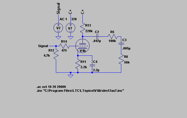
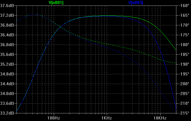
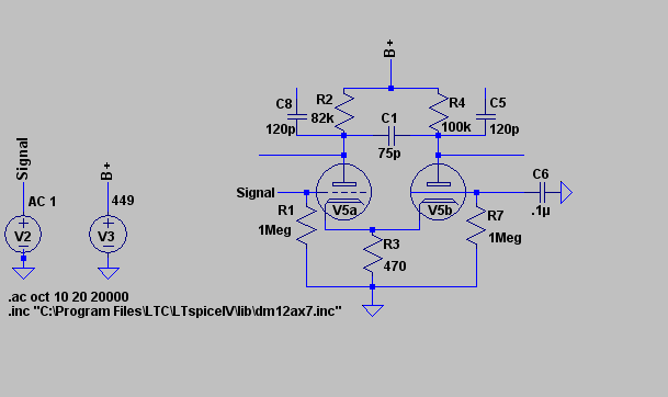
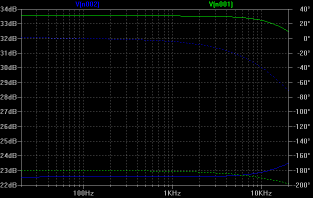
 ) change the .005µF cap on the output of the FX loop recovery stage to a 50pF cap. the nearest 5% standard value, 51pF or 10% standard value, 47pF should work fine too. This should stop the attenuation of all the midrange and high range through the FX loop while still bleeding off enough high range frequencies to prevent instability.
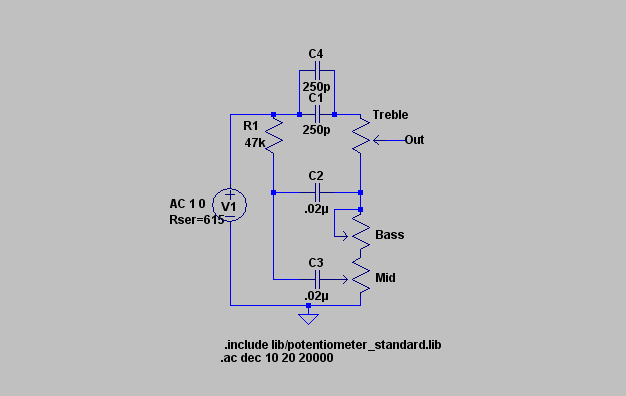
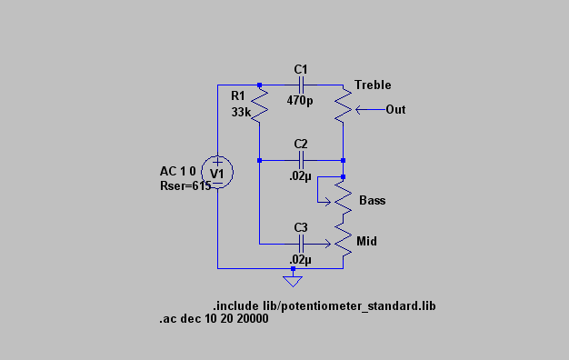
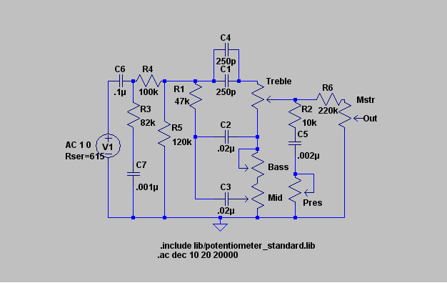
 Nice work with the tone stack, i'll look it over more when it's not so late