Mark IIC/C+ and III Power Section 1.5K Resistor Placement

The Boogie Board

Help Support The Boogie Board:

This site may earn a commission from merchant affiliate links, including eBay, Amazon, and others.

jrb32

Well-known member
Joined
Jan 31, 2018
Messages
218
Reaction score
13
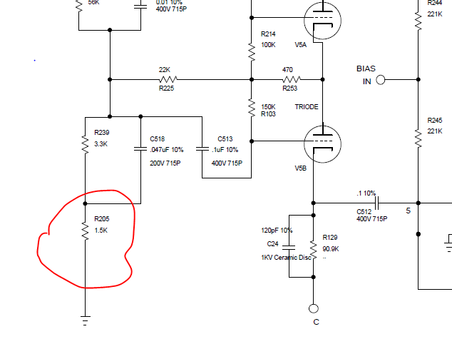
One for the engineers out there! If you look up any schematic out there for the IIC+ and the III you'll see there is a 1.5K resistor in the power section going to ground. The IIC+ and III power sections are identical in these schematics with this 1.5K going to ground in both.

However, I've traced a IIC and compared to an upgraded IIC+ and noticed a big difference between the two in the placement of this 1.5K resistor as follows:

IIC+:
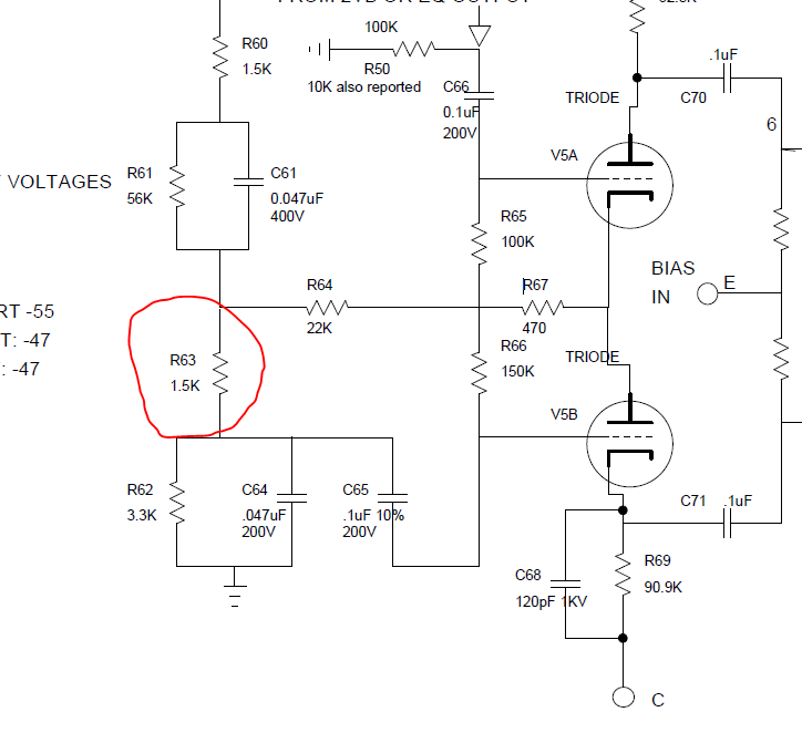
IIC-Power-Section.png


III:
III-Power-Section.png


I had already done a III+ mod with everything else identical to a IIC+, but left this 1.5K resistor stock until I made this discovery this week. I changed its placement in the power circuit of my III+ to be the same as the IIC+ this morning and noticed a massive change in sound! As in the amp is brighter and more trebley, it starts to distort on the clean channel around 7-8 on Volume 1 now and I have to turn it down to get a really nice clean. Overall it's less bold but more vintage sounding and feels a lot different.

This 1.5K resistor is left going to ground by Mike B when he does the III+ mod and also goes to ground in the Mark IV. Is this something that was a mistake by Boogie when moving to the III from using the mistaken schematics (I would assume they have some kind of master copy of a IIC/IIC+ design but you never know it could be in Mike B's head and they missed this!) or is this an upgrade due to a better power section design in the III and later?

I'm probably going crazy and I will put it back to stock just to confirm but is there anything from an engineering point of view that would explain this and whether one is better than the other, or is this so negligible a change that shouldn't have any effect?
 
I might have already asked you but is this something unique to the C+ upgrades or do you have photos of stock C+ amps with it too?
 
Hey guys recently purchased a C+, not an upgrade, and sent it to Mike B for complete check up, much to my surprise he stated there were a couple of versions of the C+ as it evolved and asked if I want d mine changed as mine is a later serial number towards end of run. I will include below his email to me, sadly I didn’t ask what the change was but sounds close to what you are describing, hope this helps:

Hi Mark,
I have your amp just about ready, just needs a play test. See the repair notes below.
I do have a question for you as long as it is here. We made the C+ simul amps two ways as far as brightness, you may have read of this?
After a few + amps we harkened back to the simul 2B were made the preamp brighter for balance with the thicker sound of simul. So we began to make the C+ brighter and yours is the brighter. Great for the crunch/metal tones but for the classic more vocal tones the darker (same as 60w and 100w) is usually desired. Two little parts, so leave it bright for you? or would you like warmer/smoother?

thanks, mike
 
That resistor is part of the tuned resonance portion of the global negative feedback loop. Placement either before or after that cap/resistor filter will have a distinct effect. The heart of the C+ and Mark III tightness is the fully realized resonance tuned negative feedback loop. This is sort of the secret sauce that separates the Mark IIC's and after from previous Mark series amps...

*You should see another 3.3k ohm resistor in series to the output transformer secondary. That series resistor and the 1.5k shunt resistor you are referencing are the heart of the negative feedback loop. The additional components are to shape the frequency response of the loop...
 
Hey guys recently purchased a C+, not an upgrade, and sent it to Mike B for complete check up, much to my surprise he stated there were a couple of versions of the C+ as it evolved and asked if I want d mine changed as mine is a later serial number towards end of run. I will include below his email to me, sadly I didn’t ask what the change was but sounds close to what you are describing, hope this helps:

Hi Mark,
I have your amp just about ready, just needs a play test. See the repair notes below.
I do have a question for you as long as it is here. We made the C+ simul amps two ways as far as brightness, you may have read of this?
After a few + amps we harkened back to the simul 2B were made the preamp brighter for balance with the thicker sound of simul. So we began to make the C+ brighter and yours is the brighter. Great for the crunch/metal tones but for the classic more vocal tones the darker (same as 60w and 100w) is usually desired. Two little parts, so leave it bright for you? or would you like warmer/smoother?

thanks, mike

A couple of versions of the C+? More like about five or six! Although mainly due to the voltage rails, ever increasing the voltage to the different 12AX7 power rails by using 1K resistors instead of 5.6K between the 30uF filter caps. Then you've got all the component type differences and then some weird values of a couple of components I've seen that vary. Anyway!

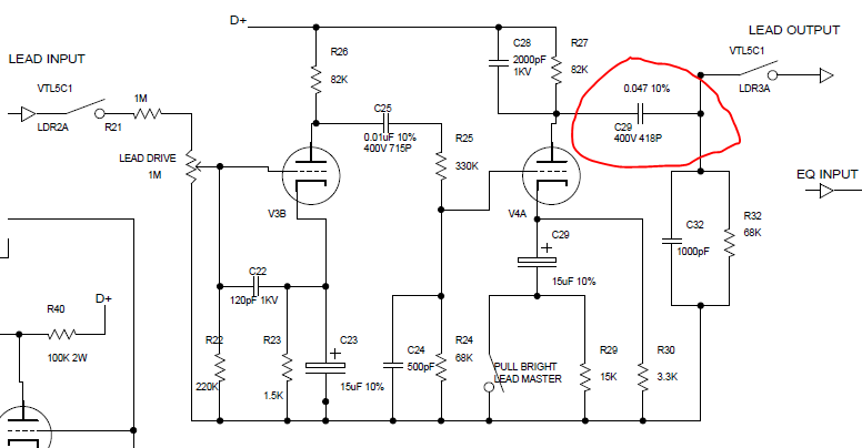
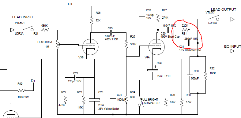
Regarding the brightness Mike B is talking about I'm not 100% correct as he talks about the preamp section, but I'm pretty sure it refers to this:

IIC Lead:

IIC-Lead.png


IIC+ Lead

IIC-Simul-Lead.png


I noticed that the circled 220K/250pF above is something that was added later in the lead section for the C+, and was not in the original C and I don't think would have been in the early C+ upgrades, as to put these in involves using a short cap and cramming 'two little parts' in literally, but I can't be sure. Further to this, a III 100W has these, but speaking to a board member on here in a III+ Simul Class Mike B specifically replaced these with bus wire effectively bypassing them as if they don't exist, reducing the brightness on request.

I will look into the simul IIB values info and see what I can come up with though for the preamp.

Either way that's a gem of knowledge and thank you for sharing!! You could write a book on these amps and barely scratch the surface!
 
That resistor is part of the tuned resonance portion of the global negative feedback loop. Placement either before or after that cap/resistor filter will have a distinct effect. The heart of the C+ and Mark III tightness is the fully realized resonance tuned negative feedback loop. This is sort of the secret sauce that separates the Mark IIC's and after from previous Mark series amps...

*You should see another 3.3k ohm resistor in series to the output transformer secondary. That series resistor and the 1.5k shunt resistor you are referencing are the heart of the negative feedback loop. The additional components are to shape the frequency response of the loop...

THANK YOU SO MUCH!!! I really try to understand amp design but I fail! I'll look out for that extra 3.3K resistor thanks. Any ideas why they changed the position of this 1.5K resistor on the III and IV? I honestly think it was a simple mistake from trying to put misinformation out in the schematics and this then going forward and not double checking, but I'm sure there's some technical reasoning involved right?
 
I might have already asked you but is this something unique to the C+ upgrades or do you have photos of stock C+ amps with it too?

The power section is exactly the same on the C+ upgrade as it is on the factory C+, and a IIC. The board is identical. The C+ (both stock and factory) have a 120pF moved from the 82K resistor to the 91K resistor. Apart from that, same board, same everything as a IIC.
 
jrb32 said:
That resistor is part of the tuned resonance portion of the global negative feedback loop. Placement either before or after that cap/resistor filter will have a distinct effect. The heart of the C+ and Mark III tightness is the fully realized resonance tuned negative feedback loop. This is sort of the secret sauce that separates the Mark IIC's and after from previous Mark series amps...

*You should see another 3.3k ohm resistor in series to the output transformer secondary. That series resistor and the 1.5k shunt resistor you are referencing are the heart of the negative feedback loop. The additional components are to shape the frequency response of the loop...

THANK YOU SO MUCH!!! I really try to understand amp design but I fail! I'll look out for that extra 3.3K resistor thanks. Any ideas why they changed the position of this 1.5K resistor on the III and IV? I honestly think it was a simple mistake from trying to put misinformation out in the schematics and this then going forward and not double checking, but I'm sure there's some technical reasoning involved right?


I believe this exact NFB matrix was questioned many moons ago on another thread where a member was having output problems with his C+. Also, Randall Aiken has a great paper he wrote about negative feedback in a tube amp and how it applies. It's cool how invested you are in sorting out the subtle differences in the C+ topology. I did this same thing with Mark I's a long time ago. You could line 10 Mark I chassis up from say 1974-1977 and each amp had major component and build differences. The art of engineering!
 
*You should see another 3.3k ohm resistor in series to the output transformer secondary. That series resistor and the 1.5k shunt resistor you are referencing are the heart of the negative feedback loop. The additional components are to shape the frequency response of the loop...

I've double checked this and this 3.3K resistor is actually a 1.5K resistor going to the presence pot and then to the transformer secondary. It is 3.3K on the early Mark IIIs, it's listed as 3.3K on the sloclones and official IIC+ schematic, but it is definitely 1.5K on all pictures of IIC+s I've seen, from factory IIC+s to IIC upgrades. Perhaps they did change this to a 3.3K in the very late IIC+ amps? I am still working off the theory that the III was based off incorrect information due to the deliberate mistakes put in the IIC+ schematic which were never verified before building the III.

I believe this exact NFB matrix was questioned many moons ago on another thread where a member was having output problems with his C+. Also, Randall Aiken has a great paper he wrote about negative feedback in a tube amp and how it applies. It's cool how invested you are in sorting out the subtle differences in the C+ topology. I did this same thing with Mark I's a long time ago. You could line 10 Mark I chassis up from say 1974-1977 and each amp had major component and build differences. The art of engineering!

Thanks I'll read that and try and get my head around the NFB. Yeah tell me about it! I've found loads of stuff already with different C+s I've seen pictures of but basically I really want to document this as much as possible and allow others an easy way to do this too (board layouts and corresponding decent schematics to double check values easily) so I'll upload those once I'm done with the info I've found.

Schematic here if you're interested:

IIC+ schematic: https://drive.google.com/open?id=1ieTnMLeSiNDoXu_9Or0ky2RIDwbLAcUQ

My next step is the other vintage boogies...

Thanks,

Jon
 
Mike B says the placement of the two doesn't really matter as they're in series. It's still something I like to do on a III+ to make it as close as possible. I will double check this on mine to make sure there is definitely no difference in sound. Try both in a scientific manner and report back.
 
I had already done a III+ mod with everything else identical to a IIC+, but left this 1.5K resistor stock until I made this discovery this week. I changed its placement in the power circuit of my III+ to be the same as the IIC+ this morning and noticed a massive change in sound! As in the amp is brighter and more trebley, it starts to distort on the clean channel around 7-8 on Volume 1 now and I have to turn it down to get a really nice clean. Overall it's less bold but more vintage sounding and feels a lot different.

I'm interested in this mod for my Red Stripe Simulclass, I'd like to be able to get some break up on R1. Are you able to walk me through how you changed the 1.5k resistor placement. Thanks.
 
Forgive me for bumping in but for what it's worth, my relatively early C+ (# 12732) has a 3.3k going to my presence. What would a 1.5k sound like there?
 
One for the engineers out there! If you look up any schematic out there for the IIC+ and the III you'll see there is a 1.5K resistor in the power section going to ground. The IIC+ and III power sections are identical in these schematics with this 1.5K going to ground in both.

However, I've traced a IIC and compared to an upgraded IIC+ and noticed a big difference between the two in the placement of this 1.5K resistor as follows:

IIC+:
IIC-Power-Section.png


III:
III-Power-Section.png


I had already done a III+ mod with everything else identical to a IIC+, but left this 1.5K resistor stock until I made this discovery this week. I changed its placement in the power circuit of my III+ to be the same as the IIC+ this morning and noticed a massive change in sound! As in the amp is brighter and more trebley, it starts to distort on the clean channel around 7-8 on Volume 1 now and I have to turn it down to get a really nice clean. Overall it's less bold but more vintage sounding and feels a lot different.

This 1.5K resistor is left going to ground by Mike B when he does the III+ mod and also goes to ground in the Mark IV. Is this something that was a mistake by Boogie when moving to the III from using the mistaken schematics (I would assume they have some kind of master copy of a IIC/IIC+ design but you never know it could be in Mike B's head and they missed this!) or is this an upgrade due to a better power section design in the III and later?

I'm probably going crazy and I will put it back to stock just to confirm but is there anything from an engineering point of view that would explain this and whether one is better than the other, or is this so negligible a change that shouldn't have any effect?
My 2:90 power amp uses both. One in Ch. A and the other in Ch. B .
 

Latest posts

Back
Top