LSC Bias Mod Kit?

The Boogie Board

Help Support The Boogie Board:

This site may earn a commission from merchant affiliate links, including eBay, Amazon, and others.

nitrous12

Active member
Joined
Feb 9, 2013
Messages
37
Reaction score
0
So Mansfield is no longer around selling those handy little bias mod kits.
Is anyone aware of an equivalent replacement? If not I am likely going to source the resistor and pot needed myself and go for it.
I get what Boogie is after for safety and convenience, but I hate cold tubes and really want the ability to dial the bias into the sweet spot. I have been doing it on my amps for years.
 
Well for anyone interested I am going to do this on my own. Its really just 2 parts...a 10K resistor (will have a 15K on hand too just in case the fixed value needs to be higher) and a 10K trim pot.
I will document along the way. Just ordering things this weekend so I likely won't tackle it for at least a week.
 
I posted a topic asking how to make one but to no avail. I'm interested in this! Good luck :D
 
I just looked up your post about this.
You said you have a friend that is electronically savy...he should definitely be able to do this for you.

The Mansfield kit was just a pot (adjustable resistor) and a fixed resistor of some value soldered to a small circuit board with 2 leads coming off of it. There is a specific 22K resistor in the amp that gets pulled out and the two leads from that circuit board go in its place. Now instead of a fixed 22K in that spot you have a resistor that can vary from say 20K up to 35K allowing you to set the bias across a wide range.

There are pics in the main threads about this that clearly show you how to find that 22K resistor. The Mansfield kit just took some of the work of knowing what to do with the trim pot out of the equation and made it easier to mount that board wherever and easily work with flexible leads to solder in.
 
nitrous12 said:
I just looked up your post about this.
You said you have a friend that is electronically savy...he should definitely be able to do this for you.

He is very electronically savy. However, If I don't present him with ALL the info he'll tell me to take a hike, haha.

nitrous12 said:
The Mansfield kit was just a pot (adjustable resistor) and a fixed resistor of some value soldered to a small circuit board with 2 leads coming off of it. There is a specific 22K resistor in the amp that gets pulled out and the two leads from that circuit board go in its place. Now instead of a fixed 22K in that spot you have a resistor that can vary from say 20K up to 35K allowing you to set the bias across a wide range.

There are pics in the main threads about this that clearly show you how to find that 22K resistor. The Mansfield kit just took some of the work of knowing what to do with the trim pot out of the equation and made it easier to mount that board wherever and easily work with flexible leads to solder in.

Thank you for simplifying it for me! I assume that I would have to use a 3.9K ohm fixed resistor just like the one pictured.

Is there a way to bias without a bias probe? If so, how? If not, would a cheap one suffice? Where can I find a small pcb like that?
 
Are you saying 3.9K based on the small resistor on the Mansfield board? I haven't gone back to look at what was on there. The tech I consulted with suggested a 10K or 15K fixed and a 10K trim pot that has the screw on the side.

Resistors are super cheap so I'll probably buy a few just in case, but you are putting a variable resistor that can vary to a higher ohm reading than that existing 22K so 10K + the 10K sweep should do it.

I don't know how you would bias without a probe. I bought one of the Weber Bias-Rites many years ago and it has been extremely valuable and paid for itself long ago. That along with a Fluke meter and I am good. You can get cheaper meters that will do this job for you...I got mine through work.

You don't really need that pcb. Use the side screw trim pot so you can lay it down with the screw up...legs will be out to the side. Use glue to secure it wherever you can close to its place in the circuit. One leg will connect to one side of that old 22K resistor spot. The other leg you need on the trim will have the fixed 10K resistor soldered on...the other end of that 10K goes to the other side of where the 22K was. There are 3 legs on the trim pot. I don't recall which you need. I think its 1 and the middle one, but I was just going to temporarily connect it up and measure with my meter to see that it is doing what I think it should.

I should mention that I am a novice at this. Anyone with experience reading probably already sees that. I studied electronics back in the 90s and hated it and moved onto something else. But I understand some extreme basics and I can solder and use a meter for some things. Thats all been enough to cover my biasing needs so far and seeing what is involved here I am comfortable doing this.
 
nitrous12 said:
Are you saying 3.9K based on the small resistor on the Mansfield board? I haven't gone back to look at what was on there. The tech I consulted with suggested a 10K or 15K fixed and a 10K trim pot that has the screw on the side.

Resistors are super cheap so I'll probably buy a few just in case, but you are putting a variable resistor that can vary to a higher ohm reading than that existing 22K so 10K + the 10K sweep should do it.

That's correct, Nitrous. The resistor on the Mansfield board appears to be a 3.9K resistor. However, I understand what you are saying. Using a 10K fixed resistor and a 10K(minimum) pot would give me a starting resistance of 20K.

nitrous12 said:
I don't know how you would bias without a probe. I bought one of the Weber Bias-Rites many years ago and it has been extremely valuable and paid for itself long ago. That along with a Fluke meter and I am good. You can get cheaper meters that will do this job for you...I got mine through work.

How about this one? Is that a fair price or should I be able to find one around here (Toronto, Canada)?

http://www.ebay.ca/itm/Tube-amp-bias-test-probe-6l6-el34-kt88-or-6bq5-el84-/290850206890?pt=Vintage_Electronics_R2&hash=item43b805f4aa&_uhb=1#ht_703wt_1397

Would I just need that and a multimeter?
 
It certainly looks pretty similar to what I have. Can't speak to the quality though...

It 'should' work for you.
 
Check out the sticky in the Rectifier section on bias modding Rectifiers.

Same concept and they are doing it with their own purchased parts.
Between that and what is documented in this section with the Mansfield kit we should be good.
 
Penguin said:
That's correct, Nitrous. The resistor on the Mansfield board appears to be a 3.9K resistor. However, I understand what you are saying. Using a 10K fixed resistor and a 10K(minimum) pot would give me a starting resistance of 20K.

Just a word of caution. I am no expert and haven't tried this kind of mod but I was under the distinct impression that the fixed resistor is placed in parallel with the variable resistor, and is there as a safety precaution in case the variable resistor, (aka pot), should fail, so I think the logic in your statement above is incorrect.
 
Well after some more reading of my own I would agree some of my thinking was not correct, but I wasn't really off on what you are pointing out. That said, you are not incorrect about using a resistor in parallel to the pot.

You can use a higher value pot and put a resistor in parallel. You can also tie the unused end to the wiper so that if the wiper goes out internally the full value of the pot is seen.
But in the case of going with a pot and resistor in series...if the pot takes a poop for some reason you should be left with the value of the fixed resistor.

I had it in my head that you raise the value of the resistance to bring the bias up, but the opposite is true. I think I am going to ask around a bit more to figure out exactly how I am going to do it meaning which value pot and resistor and wired in which way. I think there are a few ways to do this and i want to make sure I give myself the sweep range needed, but also some protection.
 
nitrous12 said:
Well after some more reading of my own I would agree some of my thinking was not correct, but I wasn't really off on what you are pointing out. That said, you are not incorrect about using a resistor in parallel to the pot.

You can use a higher value pot and put a resistor in parallel. You can also tie the unused end to the wiper so that if the wiper goes out internally the full value of the pot is seen.
But in the case of going with a pot and resistor in series...if the pot takes a poop for some reason you should be left with the value of the fixed resistor.

I had it in my head that you raise the value of the resistance to bring the bias up, but the opposite is true. I think I am going to ask around a bit more to figure out exactly how I am going to do it meaning which value pot and resistor and wired in which way. I think there are a few ways to do this and i want to make sure I give myself the sweep range needed, but also some protection.

The amp bias does get hotter as you raise the resistance, hence if the pot goes open circuit, (infinite resistance) you will blow the output tubes. That is why putting a resistor in parallel is advantageous as you can put a lower value resistor in parallel, (which is why the Mansfield kit used a 3.9K resistor), and therefore protect the amp if the pot fails. It's all to do with the bias supply being a negative potential.
 
thom said:
The amp bias does get hotter as you raise the resistance, hence if the pot goes open circuit, (infinite resistance) you will blow the output tubes. That is why putting a resistor in parallel is advantageous as you can put a lower value resistor in parallel, (which is why the Mansfield kit used a 3.9K resistor), and therefore protect the amp if the pot fails. It's all to do with the bias supply being a negative potential.

Thank you for that valuable information, Thom! Pardon my ignorance, but does the value of the fixed resistor matter? What would be a safe value to use? I'm surprised a 3.9K resistor is fine in place of Mesa's stock 22K resistor.

Slightly Off Topic: Is it necessary to measure the plate voltage when biasing or should all Lonestars produce roughly the same reading?
 
Penguin said:
thom said:
The amp bias does get hotter as you raise the resistance, hence if the pot goes open circuit, (infinite resistance) you will blow the output tubes. That is why putting a resistor in parallel is advantageous as you can put a lower value resistor in parallel, (which is why the Mansfield kit used a 3.9K resistor), and therefore protect the amp if the pot fails. It's all to do with the bias supply being a negative potential.

Thank you for that valuable information, Thom! Pardon my ignorance, but does the value of the fixed resistor matter? What would be a safe value to use? I'm surprised a 3.9K resistor is fine in place of Mesa's stock 22K resistor.

Slightly Off Topic: Is it necessary to measure the plate voltage when biasing or should all Lonestars produce roughly the same reading?

Hi Penguin

The reason the 3.9K resistor is OK is because it is in parallel with the pot. If the pot goes open circuit then the 3.9K resistor is there as a back up. In the event that the bias pot fails the 3.9K resistor will allow through a high bias current that will make the amps bias very cold. The amp may not sound good, but it wil not blow. That is the job of the 3.9K resistor placed in parallel with the bias pot. This is somewhat counter intuitive, but a high bias current makes the amp run colder, because, as I said before the bias current is -ve............ I recommend that you research Ohms law to get your head round how resistance works when resistors are placed in parallel against when they are placed in series. I would also say that I am not an amp tech, and I would encourage you to send a respectful post to the amplifier technical section of the gearpage, where there are many tube amp experts who can explain this stuff much better than I can......
 
Did you end up doing the mod, Nitrous? If so, how did it turn out?

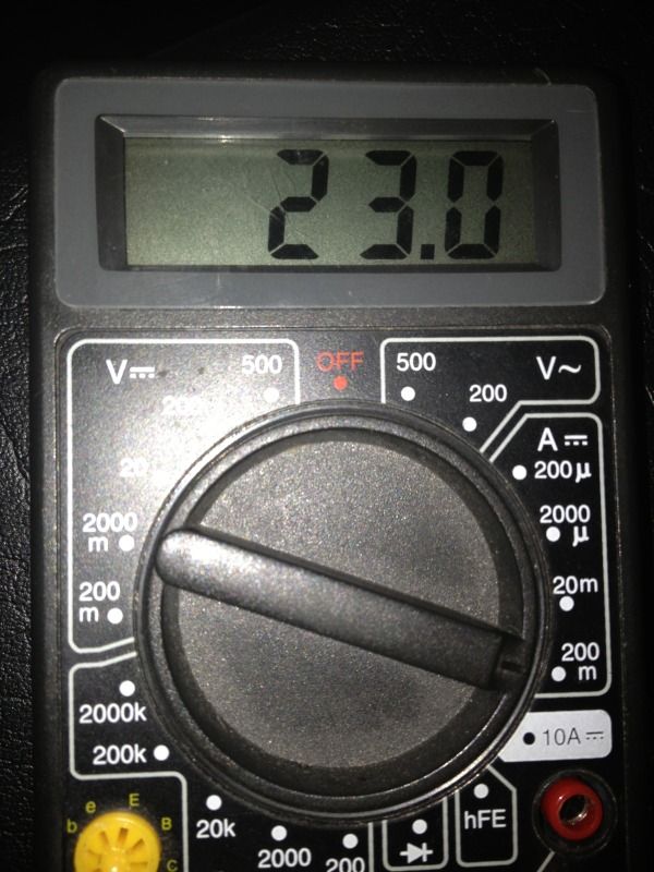
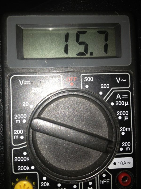
I read in the original bias mod thread that the mA reading should drop when you switch from 50W to 100W. Oddly enough, mine did the opposite.

100W setting
IMG_1399_zps8a0006a5.jpg


50W setting
IMG_1398_zpsbd27a10d.jpg


The measurement was taken from the power tube closest to the rectifier tube. What is going on here? :?
 
So is the bias mod a dead issue now, or does making your own "kit" make sense?

Appreciate the collective wisdom!
 
Back
Top