You are using an out of date browser. It may not display this or other websites correctly.
You should upgrade or use an alternative browser.
You should upgrade or use an alternative browser.
Complete Mark III Schematic
- Thread starter >Photi G<
- Start date


Help Support The Boogie Board:
This site may earn a commission from merchant affiliate
links, including eBay, Amazon, and others.
>Photi G<
Well-known member
The green stripe is exactly the same, except the Class A tubes are wired in Pentode, so their Screen resistors would be wired in parallel with the Class AB tubes instead in parallel with the OT primary.
>Photi G<
Well-known member
Good news everybody, my revised edition will be posted in the coming days! New version includes some schematic tweaks where I found errors, and voltage readings! Unfortunately, I couldn't label part numbers such as C30, or R125, etc. since some of the designators aren't even printed on my board, or are covered by other components. I also originally planned to create a board layout, but that would require me to have the amp on my bench in pieces for a while, and that would interrupt my playing schedule :lol: Plus, I still need a decent soldering iron.
I've been in limited contact with member McBarry over the subject, but probably due to my stupidity, communication has dropped. I invite him to post his voltages which he measured a while back for comparison. So now you have 2 points of reference if you ever need to scope/meter your Mark III. Cya in a few days while I finalize it all!
I've been in limited contact with member McBarry over the subject, but probably due to my stupidity, communication has dropped. I invite him to post his voltages which he measured a while back for comparison. So now you have 2 points of reference if you ever need to scope/meter your Mark III. Cya in a few days while I finalize it all!
McBarry
Well-known member
Hi folks,
I'll have mine on the bench hopefully next wk and will throw up my voltages for a 1k sine wave through the amp.
I'm happy to insert any particular signal U all desire - let me know..
Photi, I'll measure all my pots and let U know..
It's worth mentioning I consider myself a noob compared to the likes of BoogieBabes, Monsta et al, - figures from such folks would be also gretly recieved, esp from myself and I'm sure others..
The IIA is going on the bench too - needs a little hum-ectomy..
While there I'll chase same signal and post readings, given there seems a growing group of IIA afficianodo's..LOL
Ned/mods, I'm not sure it warrants a new thread - thoughts??
DB
>Photi G<
Well-known member
I didn't measure signal voltages on mine, since I don't have a sine generator. I tried my hand at measuring the pots, but they need to be completely isolated from the circuit to be done accurately, and I wasn't looking for that kind of tinkering at the moment.
McBarry
Well-known member
Hi folks,
here's my initial voltages, I will add the preamp in the next few days.
I've also done the signal trace through the preamp up to the m/vol point.
A huge debt of thanks to George for his original work.. Brilliant!!
Here's a direct link to the pic I've done, below should appear the embedded pic.
Hope it's of help, Dave
http://i830.photobucket.com/albums/zz227/McBarry01/p2McBarryREDsrtipe.jpg
>Photi G<
Well-known member
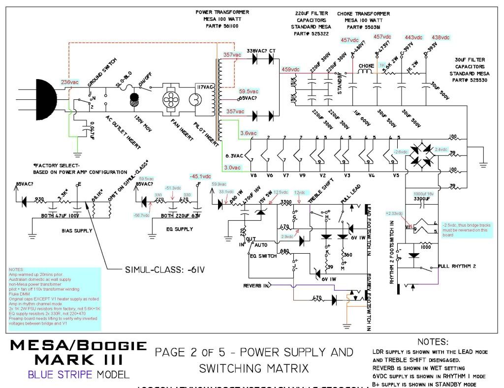
Here's a little teaser of what I've been working on:

All those little blue leaders are DC voltages. The rest of the pages might take a while; I'm having some technical difficulties with AutoCAD. Things should come together shortly though. A PDF version is available here so it isn't so pixellated as you zoom in. http://premium1.uploadit.org/pRPLbLNs//teaser.pdf
All those little blue leaders are DC voltages. The rest of the pages might take a while; I'm having some technical difficulties with AutoCAD. Things should come together shortly though. A PDF version is available here so it isn't so pixellated as you zoom in. http://premium1.uploadit.org/pRPLbLNs//teaser.pdf
McBarry
Well-known member
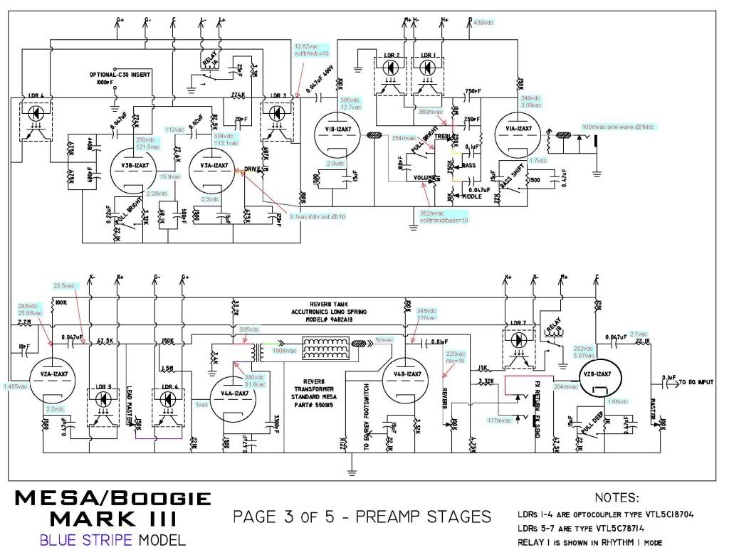
OK, preamp is done for dc supplies and also signal transit from input through to master vol pot.
Incuding path through lead channel up to it's master vol and reverb circuit with rev pot @10.
I'm a little suspicious at 5mv signal after rev tank, but given the impedances there, it might be OK.
Of interest is why the LV bridge output gets inverted after the smoothing cap and beyond. Mysterious...
Also, could someone check their physical board and verify the smoothing cap after low voltage bridge - MINE is 1000uf/16v, but George's says 3300uf and my Musicparts schematic says 3300uf also..
Here's the pic and a link, Dave
http://i830.photobucket.com/albums/zz227/McBarry01/p3McBarryREDstripejpg.jpg
chipaudette
Well-known member
Hi,
Thanks for the work.
I see that your images clearly state that this is for a blue stripe, yet the file name of the pictures says red stripe.
Is blue the correct one?
Chip
Thanks for the work.
I see that your images clearly state that this is for a blue stripe, yet the file name of the pictures says red stripe.
Is blue the correct one?
Chip
chipaudette
Well-known member
Also,
On the bottom half of your latest page (page 3), the traces are a bit confusing to me. Could you recheck your drawings in the following areas:
1) Relay 1B: You've shown nothing powering the coil. Also, you've shown M+ being attached to the signal pathway, both of which are connected to ground. I'm not sure that you meant to do that.
2) Signal to FX Send: at the junction right after the 3.32K resistor, there's a junction. Is that supposed to be a junction, or is the wire to the send supposed to jump over the wire from the reverb. I don't know what's right here. If it does jump, then the reverb signal goes around the Effects Loop (by connecting only at the "Return")...so it probably does connect here.
3) Reverb vs FX Loop: This schematic says that the reverb is before the effects loop, which is weird. Usually, the FX loop is before the reverb so that your signal is effected first and then reverb is applied. I have seen this in other Mark III schematics, so it could very well be true for the Mark III. I'm just asking for your confirmation.
Thanks again for the hardwork. These are intended very much as friendly questions.
Chip
McBarry
Well-known member
Hi Chip, I'll let George answer to original traces, but I can advise thus:
There IS a junction at FX jacks - 2 black wires - one from rev pot, other from board, the Musicparts and Mesa schematics are hard to follow here. Here's a pic of the FX jacks showing red incoming wire from board and the 2 black wire.

Reverb IS before the FX loop, but again, both the Musicparts and Mesa schematics are little hard to follow, and my physical board is hard to follow there courtesy of a birds nest of LDR's, orange drops and underside tracks.
Now, my V1p9 is definitely positive, thus the LV bridge is drawn wrong polarity on Musicparts, Mesa and likely George's diagrams.
Chip, is your electro after this bridge 1000uf or 3300uf per the diagrams??
And yeah, I welcome good critiquing - it can only benefit all of us i reckon..
Keep the observations coming..
Dave
There IS a junction at FX jacks - 2 black wires - one from rev pot, other from board, the Musicparts and Mesa schematics are hard to follow here. Here's a pic of the FX jacks showing red incoming wire from board and the 2 black wire.
Reverb IS before the FX loop, but again, both the Musicparts and Mesa schematics are little hard to follow, and my physical board is hard to follow there courtesy of a birds nest of LDR's, orange drops and underside tracks.
Now, my V1p9 is definitely positive, thus the LV bridge is drawn wrong polarity on Musicparts, Mesa and likely George's diagrams.
Chip, is your electro after this bridge 1000uf or 3300uf per the diagrams??
And yeah, I welcome good critiquing - it can only benefit all of us i reckon..
Keep the observations coming..
Dave
>Photi G<
Well-known member
chipaudette said:Also,
On the bottom half of your latest page (page 3), the traces are a bit confusing to me. Could you recheck your drawings in the following areas:
1) Relay 1B: You've shown nothing powering the coil. Also, you've shown M+ being attached to the signal pathway, both of which are connected to ground. I'm not sure that you meant to do that.
2) Signal to FX Send: at the junction right after the 3.32K resistor, there's a junction. Is that supposed to be a junction, or is the wire to the send supposed to jump over the wire from the reverb. I don't know what's right here. If it does jump, then the reverb signal goes around the Effects Loop (by connecting only at the "Return")...so it probably does connect here.
3) Reverb vs FX Loop: This schematic says that the reverb is before the effects loop, which is weird. Usually, the FX loop is before the reverb so that your signal is effected first and then reverb is applied. I have seen this in other Mark III schematics, so it could very well be true for the Mark III. I'm just asking for your confirmation.
Thanks again for the hardwork. These are intended very much as friendly questions.
Chip
Good questions, chip, let me clear them up for you.
My reference amp is a Blue Stripe, McBarry's is a Red. He simply borrowed my drawings, and pasted his voltages on it, that's all.
1.) There is no power being shown to Relay 1B because it is the second half of Relay 1A. They are a DPDT switch actuated by a single coil, since they are a single component much like 2 OP Amps in a TL272 chip, or two triodes in a 12AX7. I felt it was redundant to redraw the coil supply, much like it is redundant to redraw the power/ground of a dual OP Amp, or the heaters of a dual triode.
2.) There is a junction at the FX send. All overlapping traces on my drawings are represented by a semicircle "jumping" over the trace underneath it.
3.) The reverb is in parallel with the dry signal before the FX loop. A divider network feeds a low level signal from V2A to V4A, and passes a padded dry signal along side of it, straight to the FX send. V4B outputs a wet signal then blended with the dry before the FX send. This is a design error in the Mark III, which causes weak reverb, and sometimes, distortion in the FX loop. The blend was fixed on the Mark IV and later models, but the Reverb was always Pre-FX.
chipaudette
Well-known member
McBarry:
I actually don't have a Mark III. I have an older Mark. I'm just a guy who's really interested in the circuit changes over the years I like to mod my own amps, so this kind of comparative study helps me understand what changes can make what kind of sound.
Chip
Chip, is your electro after this bridge 1000uf or 3300uf per the diagrams??
I actually don't have a Mark III. I have an older Mark. I'm just a guy who's really interested in the circuit changes over the years I like to mod my own amps, so this kind of comparative study helps me understand what changes can make what kind of sound.
Chip
chipaudette
Well-known member
>Photi G<:
Thanks for the detailed reply. I appreciate it.
With respect to Relay 1B, with the relay in the position shown in the schematic, it shows M+ as being routed (through the relay) directly to ground. I don't know what M+ is (I don't have the full schematic), but it is drawn as if it were a voltage rail. One doesn't usually just send a voltage rail to ground. Is this really what happens? If so, where is M+ coming from?
Thanks. I love circuit talk.
Chip
McBarry
Well-known member
Cool Chip,
which Mark do you have?
George, and anyone else,please can U have a look and tell me what value capacitor U have after the low voltage bridge - 1000uf/16v or 3300uf/16v?
Its on the preamp board and it's the single big electro next to the 3x 30uf/500v caps..
Dave
which Mark do you have?
George, and anyone else,please can U have a look and tell me what value capacitor U have after the low voltage bridge - 1000uf/16v or 3300uf/16v?
Its on the preamp board and it's the single big electro next to the 3x 30uf/500v caps..
Dave
chipaudette
Well-known member
McBarry
I have a Mark IIC that has been upgraded by MikeB at Boogie to a IIC+. It's a 60/100, not a Simul-Class. It does have Reverb and GEQ, though. It's pretty rockin', but I actually find myself playing my (heavily modified) Fender Deluxe Reverb Reissue more often. Weird.
Chip
which Mark do you have?
I have a Mark IIC that has been upgraded by MikeB at Boogie to a IIC+. It's a 60/100, not a Simul-Class. It does have Reverb and GEQ, though. It's pretty rockin', but I actually find myself playing my (heavily modified) Fender Deluxe Reverb Reissue more often. Weird.
Chip
>Photi G<
Well-known member
chipaudette said:>Photi G<:
Thanks for the detailed reply. I appreciate it.
With respect to Relay 1B, with the relay in the position shown in the schematic, it shows M+ as being routed (through the relay) directly to ground. I don't know what M+ is (I don't have the full schematic), but it is drawn as if it were a voltage rail. One doesn't usually just send a voltage rail to ground. Is this really what happens? If so, where is M+ coming from?
Thanks. I love circuit talk.
Chip
Haha, as do I. :lol:
M+ is one of the voltage rails coming off the switching matrix. If you notice the tone stack, there are two LDR's in parallel that bypass the 10meg resistor thus engaging the Treble Shift function. M+ is the voltage that is fed to the second of the two LDR's. In Rhythm 1 mode (which is shown in the schematic), M+ is shorted to ground, thus disabling the LDR and engaging the treble shift control. When in Rhythm 2 Mode, the relay changes positions, lifting the ground on an R/C system feeding V2B, and M+. This disables the Treble Shift function during R2 operation, which gives R2 its darker sound. The other LDR is tied to the Lead switching matrix, so it is active only in the Lead mode.
As many others have said, your a saint for doing the hard work to develope a correct schematic for the Mark III. That said, I've done all I can to get to the link, including paying the $$. Can't find the info anywhere using every trick in my bag.
Can anyone provide the schematic in any format? e-mail is [email protected]
Thanks for the help.
Can anyone provide the schematic in any format? e-mail is [email protected]
Thanks for the help.
McBarry
Well-known member
G'day,
tried PM but can't, so I'll send U my schematics which are correct for my particular amp soon as I get home in the morning.
regs, Dave
tried PM but can't, so I'll send U my schematics which are correct for my particular amp soon as I get home in the morning.
regs, Dave
>Photi G<
Well-known member
Oh, god, it's been too long. I haven't been active on the forum lately due to tons of things going on IRL, but I thought I'd drop by. I noticed that the file sharing site I've been using for the schems has been shut down  , so if anyone has any ideas for a new host, I'm all ears. In the meantime, I'll entertain any requests for the files via email-just pm me. Any other requests/feedback are/is appreciated as always.
, so if anyone has any ideas for a new host, I'm all ears. In the meantime, I'll entertain any requests for the files via email-just pm me. Any other requests/feedback are/is appreciated as always.Similar threads
- Replies
- 70
- Views
- 10K
- Replies
- 2
- Views
- 928
- Replies
- 64
- Views
- 133K