URGENT help required...........

The Boogie Board

Help Support The Boogie Board:

This site may earn a commission from merchant affiliate links, including eBay, Amazon, and others.

52 tele

Member
Joined
Sep 28, 2010
Messages
10
Reaction score
0
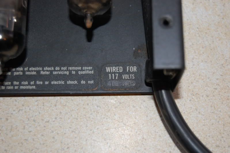
I took my 20/20 dyna watt to an amp tech yesterday to collect a step down transformer,[its a USA 117v spec and
I'm in the UK].
The guy takes the lid off to see if it could be converted to 230v,even though I know you'd need to buy 230v
transformers,anyways after much smoke and mirrors he says it can't be converted,surprise surprise.
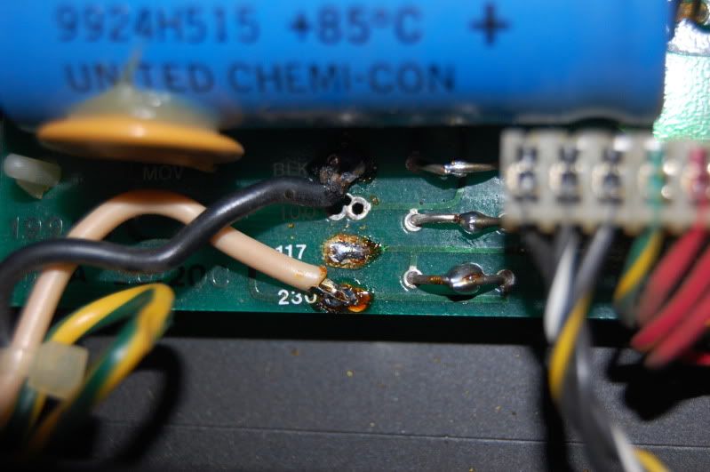
I collect my step down transformer and head home.I've just come to mount it in the rack case and I thought I'd
clean out the fan first,just having a look round and noticed that where the power cable connects to the board
the white lead has been resoldered to the 230v tag............SURELY this is wrong if its US voltage........
DSC_0215-2.jpg


DSC_0216-1.jpg


Can anyone here on the board confirm my suspicions..........the guy soldered a lead onto the tags while he was
supposedly checking it out and I strongly feel that sabotage is afoot here!! so can anybody please help me out here.
PS I've posted here and not Rack Pieces so that maybe more members might view this.
Thanks in advance.
 
Hmm, I would tend to think that is not correct. Hopefully someone with a 20/20 will open it up and confirm.

Looking at the schematic it appears that the amp can indeed be re-wired for 230V, but it is more complicated then just moving one wire.

The schemo lists Mesa PT#561020 for both the 120V domestics and the 220-240V exports.
The schematic is in this thread, first post: http://music-electronics-forum.com/t22622/

I believe the one in question in your pic adds the connections for the 3 caps on the primary side when connected to "230". If this schematic is correct then any good tech should be able to mod the amp.

I would think that the wiring from the primary side of the PT that needed to be moved would also have connections like the one in your pic. There may also be jumpers or components that need to be added or removed.

Dom
 
Anyways I resoldered the white wire to the 117v tag on the board and tried the rig out earlier........hahahahaha.....
absolutely stellar,I'm so made up with this rig I can't even tell ya and I have'nt even opened it up....

By the way,the so called tech said that if I'm only using 1 channel that I should remove the 2 power tubes from
the unused channel..........wtf.....I just shut the volume and turned up the presence control and it seems fine.....
After all I think the guys at Mesa probably KNOW what THEY are talking about......

Any thoughts on the initial wiring concern still greatly appreciated........
 
Looking closeley at your board, you can see that both the 117 and 230V connections are actually connected together by the board due to the odd looking wire link. So it doesn't matter which one the white wire is soldered to.
 
J.J said:
Looking closeley at your board, you can see that both the 117 and 230V connections are actually connected together by the board due to the odd looking wire link. So it doesn't matter which one the white wire is soldered to.
That is correct. The 'odd looking wire links' are jumpers that have been cut - probably to try to convert it to the other voltage - and then soldered back together. I don't have a schematic for the 20/20 but from the layout of the jumper points it looks like it might be designed for a 'dual primary' PT where there are two 117V windings that are connected in parallel for 117V and in series for 230V. I can't tell for sure from that pic though, and I wouldn't like to assume so.

I might be inclined to seek a second professional opinion on it though. It would strike me as surprising that it should have clearly marked 117 and 230V points on the board if it was not capable of being wired for both.
 
94Tremoverb said:
J.J said:
Looking closeley at your board, you can see that both the 117 and 230V connections are actually connected together by the board due to the odd looking wire link. So it doesn't matter which one the white wire is soldered to.
That is correct. The 'odd looking wire links' are jumpers that have been cut - probably to try to convert it to the other voltage - and then soldered back together. I don't have a schematic for the 20/20 but from the layout of the jumper points it looks like it might be designed for a 'dual primary' PT where there are two 117V windings that are connected in parallel for 117V and in series for 230V. I can't tell for sure from that pic though, and I wouldn't like to assume so.

I might be inclined to seek a second professional opinion on it though. It would strike me as surprising that it should have clearly marked 117 and 230V points on the board if it was not capable of being wired for both.


Thanks 94Trem,it can indeed be wired for 230v using the original transformers using the in series wiring you suggested.
Its not straight forward but I have spoke to a Boogie specialist and he can do the work for the same price as a step
down transformer..........a job for the new year.
 
Back
Top