Hi everyone,
I am trying to create a simple guide that can be useful to identify/test all the LDRs present on both the mainboard and TX4 board and, hopefully, find equivalent - still in production - components. All the info below come from having a look at my 2001 unit, SN: 7590.
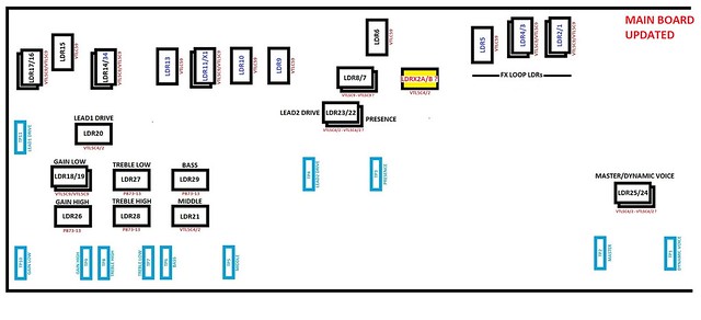
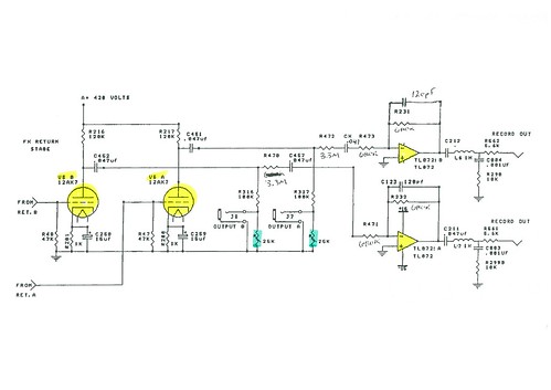
All the LDRs are one of the three models: VTL5C9, VTL5C4/2 and P873-13 (latter ones used for tone stacks only). So far, I've been able to identify most but not all them, due to the fact that the top part of the mainboard is really hard to access and measurements can be taken only by unsoldering TX4 board. The drawings below show their position in the circuit and on the actual boards.
Schematic 1:
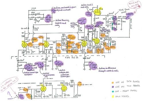
Schematic 2:
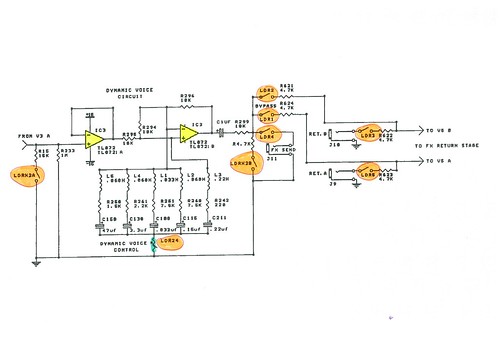
Schematic 3:
LDR Layout on Mainboard:
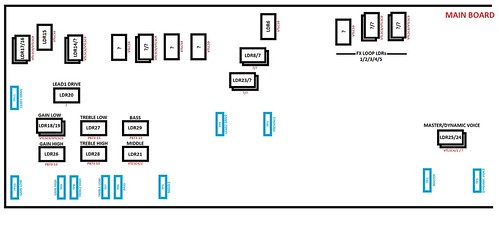
LDR Mainboard Activation Table:

LDR Layout on TX4:
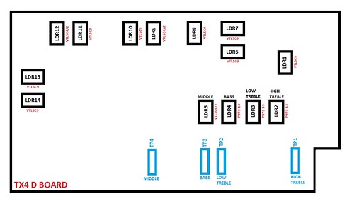
LDR TX4 Activation Table:
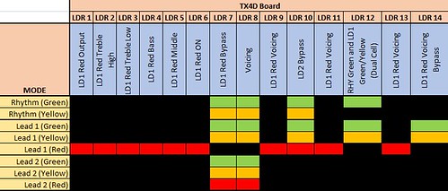
Activation voltage for all VTL5C9 LDRs seems to be 2.0V (1Mohm), for VTL5C4/2 seems around 1.6V.
Now questions that need to be clarified:
- does anyone know which LDR is which (the ones marked with a question mark)?
- on the mainboard, many of them are stacked one over the other, does that mean that the bottom ones are of the same model of the top one?
- can anyone confirm that the activation tables are correct?
- in Schematic 1, LDR9 on TX4 is shown twice, in one case it bypasses an 22kohm resistor when on LEAD1 RED mode, the other one seems to be for bypassing V4 tube (however this function seems to be achieved by LDR10 on TX4). It looks like there is a mistake there?
- most important question: what new and equivalent LDRs can be used for replacement, considering almost all of them are used for ON/OFF function only and don't need any particular calibration?
Last but not least, thanks to everyone in this forum for all the very useful info I could find!
I am trying to create a simple guide that can be useful to identify/test all the LDRs present on both the mainboard and TX4 board and, hopefully, find equivalent - still in production - components. All the info below come from having a look at my 2001 unit, SN: 7590.
All the LDRs are one of the three models: VTL5C9, VTL5C4/2 and P873-13 (latter ones used for tone stacks only). So far, I've been able to identify most but not all them, due to the fact that the top part of the mainboard is really hard to access and measurements can be taken only by unsoldering TX4 board. The drawings below show their position in the circuit and on the actual boards.
Schematic 1:

Schematic 2:

Schematic 3:

LDR Layout on Mainboard:

LDR Mainboard Activation Table:

LDR Layout on TX4:

LDR TX4 Activation Table:

Activation voltage for all VTL5C9 LDRs seems to be 2.0V (1Mohm), for VTL5C4/2 seems around 1.6V.
Now questions that need to be clarified:
- does anyone know which LDR is which (the ones marked with a question mark)?
- on the mainboard, many of them are stacked one over the other, does that mean that the bottom ones are of the same model of the top one?
- can anyone confirm that the activation tables are correct?
- in Schematic 1, LDR9 on TX4 is shown twice, in one case it bypasses an 22kohm resistor when on LEAD1 RED mode, the other one seems to be for bypassing V4 tube (however this function seems to be achieved by LDR10 on TX4). It looks like there is a mistake there?
- most important question: what new and equivalent LDRs can be used for replacement, considering almost all of them are used for ON/OFF function only and don't need any particular calibration?
Last but not least, thanks to everyone in this forum for all the very useful info I could find!


