Triaxis Optocouplers, LDRs, Relays

The Boogie Board

Help Support The Boogie Board:

This site may earn a commission from merchant affiliate links, including eBay, Amazon, and others.

Luca80

Member
Joined
Mar 6, 2014
Messages
19
Reaction score
0
Hi everyone,
I am trying to create a simple guide that can be useful to identify/test all the LDRs present on both the mainboard and TX4 board and, hopefully, find equivalent - still in production - components. All the info below come from having a look at my 2001 unit, SN: 7590.

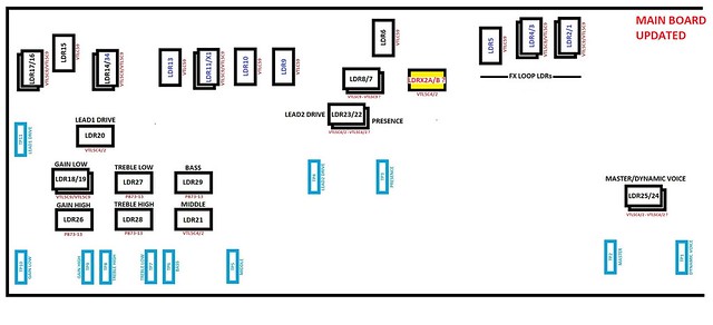
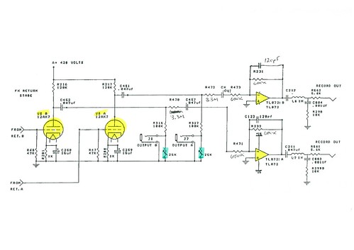
All the LDRs are one of the three models: VTL5C9, VTL5C4/2 and P873-13 (latter ones used for tone stacks only). So far, I've been able to identify most but not all them, due to the fact that the top part of the mainboard is really hard to access and measurements can be taken only by unsoldering TX4 board. The drawings below show their position in the circuit and on the actual boards.

Schematic 1:
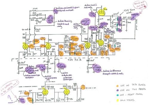

Schematic 2:
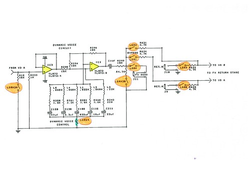

Schematic 3:

LDR Layout on Mainboard:
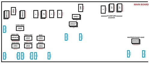

LDR Mainboard Activation Table:


LDR Layout on TX4:
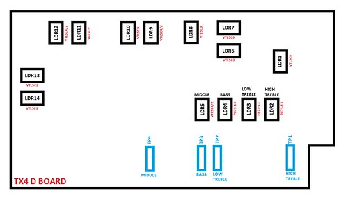

LDR TX4 Activation Table:
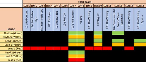

Activation voltage for all VTL5C9 LDRs seems to be 2.0V (1Mohm), for VTL5C4/2 seems around 1.6V.

Now questions that need to be clarified:
- does anyone know which LDR is which (the ones marked with a question mark)?
- on the mainboard, many of them are stacked one over the other, does that mean that the bottom ones are of the same model of the top one?
- can anyone confirm that the activation tables are correct?
- in Schematic 1, LDR9 on TX4 is shown twice, in one case it bypasses an 22kohm resistor when on LEAD1 RED mode, the other one seems to be for bypassing V4 tube (however this function seems to be achieved by LDR10 on TX4). It looks like there is a mistake there?
- most important question: what new and equivalent LDRs can be used for replacement, considering almost all of them are used for ON/OFF function only and don't need any particular calibration?

Last but not least, thanks to everyone in this forum for all the very useful info I could find!
 
does anyone know which LDR is which (the ones marked with a question mark)?

From top left:

4th block: LDR13
5th block: LDR11/Top, LDRX1/Bottom
6th block: LDR10
7th block: LDR9

FX Loop LDR from left to right:

1st block: LDR5
2nd block: LDR4/top, LDR3/Bottom
3nd block: LDR2/Bottom, LDR1/Bottom

on the mainboard, many of them are stacked one over the other, does that mean that the bottom ones are of the same model of the top one?

I think there is only one pair on the bottom left of the main board (5C9 and 5C4/2 or 5C3/2, cant remember)

what new and equivalent LDRs can be used for replacement

Vactrol
 
Thanks Synrgy77, that helped.
I suppose that LDR34 is under LDR14 at this stage (the third block from top left corner).

Re the bottom left pair you mentioned, I guess you're talking about LDR18 and LDR19, which are part of the gain section.

The Vactrol LDRs were made by Perkin Elmer, then by Excelitas, now discountinued and they are hard to find at an acceptable price.
My question is whether anyone tried other models, like X-Vive, and what is the outcome (any difference in tone and switching speed?).

One more thing, I noticed that my unit doesn't have one LDR, as per updated diagram below (the yellow one). I think it is the X2A and X2B pair, which is used to bypass the dynamic voice section. Can anyone confirm that?

Main Board LDR Layout by Luca Paltera, on Flickr
 
I suppose that LDR34 is under LDR14

Yes

Re the bottom left pair you mentioned, I guess you're talking about LDR18 and LDR19, which are part of the gain section.

Only LDR18 is used for the low gain section. LDR19, the one on top has only two legs (5C9). I looked at mine (T-7542) which is from an early 2000 production.

One more thing, I noticed that my unit doesn't have one LDR, as per updated diagram below (the yellow one). I think it is the X2A and X2B pair,

I dont have these LDR either. Mine has the FAT mode. These two LDR where present on V1 and V2 Recto. Tantalum switching capacitors shape looks different too.

I cant comment on LDR. I have some spares but only from Vactec.
 
We have the same model, mine made in November 2001, but I removed the fat mod.
 
Yeah I already went through the datasheets, as you can see, parameters are similar but not the same; that is the reason why I was asking if anyone already tried to replace the original Vactrol LDRs with one of those X-Vive ones.

Just to specify, my Triaxis works perfectly and sounds awesome, my search is about future servicing rather than an actual repair.
 
Are you sure the placement on the LDR diagram of TP6 is correct?

On my V1 triaxis the one you have listed as tp6 is tp5 & vice versa.

Currently trying to calibrate my v1 triaxis but the calibration mode seems different and i'm getting high readings for the mids changing from 980k-1.5M won't get a stable reading. I've tried two meters with the same result.

Do you have any ideas what this could be? also TP6 seems to have no effect whatsoever on the reading. I have removed the pot and checked it and it's working fine out of the amp.
 
Good point. These two trim pots are easy to find since they are identified on the board as "MD" for Mids and "B" for Bass. The calibration procedure says TP5 for Bass and TP6 for Mids.

Currently trying to calibrate my v1 triaxis but the calibration mode seems different and i'm getting high readings for the mids changing from 980k-1.5M won't get a stable reading. I've tried two meters with the same result.

There are good chances to find a bad OP Amp here ( 8 pins IC TL072). If your OP Amps are seated in DIP sockets, try to swap it with an other one to see if you're able to get good reading from LDR21 (Mid). Mids are on IC5 (TX1) if I remember. You wont find TL072 on schematics except for DV and Record Out sections and these are for audio, not for LDR. I didnt bother with their location when I faced this problem since I changed them all, but it would be a good idea to locate them. There are two Op amps per IC. For instance, IC2 controls Master Volume(LDR25) and D.V.(LDR24). IC4 controls Lead2(LDR23) and Presence(LDR22).

The TL072 setpoint for Mids is coming from IC1 and IC2 on TX3A digipots board. But if one of these two Mux/Demux IC were bad, there would be no change at audio level when changing the settings from the Mids keypad. Thats why I guess for a bad TL072.

Its the way I've followed the signal path to fix the problem you've described and the cheapest before looking at LDR.
 
Thanks a lot that is really helpful.

I will have another look tomorrow hopefully this is what i've been looking for.

I;ve noticed the dip switches. Do you know what they are for?

I think I have a few tl072 handy or should definitely have a substitute.

Thanks again.

Tony
 
I;ve noticed the dip switches. Do you know what they are for?

These switches are used to isolate some LDR during calibration. Look on top of the switch, you will see a dot built in the switch (white part on top). When the dot is visible, the switch is in operation mode. When the dot is hidden, the switch is set for calibration mode. Dont forget to turn all switches back to operation mode (dot visible) when calibration is done. Good luck !
 
Synrgy77 said:
Good point. These two trim pots are easy to find since they are identified on the board as "MD" for Mids and "B" for Bass. The calibration procedure says TP5 for Bass and TP6 for Mids.

Currently trying to calibrate my v1 triaxis but the calibration mode seems different and i'm getting high readings for the mids changing from 980k-1.5M won't get a stable reading. I've tried two meters with the same result.

There are good chances to find a bad OP Amp here ( 8 pins IC TL072). If your OP Amps are seated in DIP sockets, try to swap it with an other one to see if you're able to get good reading from LDR21 (Mid). Mids are on IC5 (TX1) if I remember. You wont find TL072 on schematics except for DV and Record Out sections and these are for audio, not for LDR. I didnt bother with their location when I faced this problem since I changed them all, but it would be a good idea to locate them. There are two Op amps per IC. For instance, IC2 controls Master Volume(LDR25) and D.V.(LDR24). IC4 controls Lead2(LDR23) and Presence(LDR22).

The TL072 setpoint for Mids is coming from IC1 and IC2 on TX3A digipots board. But if one of these two Mux/Demux IC were bad, there would be no change at audio level when changing the settings from the Mids keypad. Thats why I guess for a bad TL072.

Its the way I've followed the signal path to fix the problem you've described and the cheapest before looking at LDR.

Just reread this. The front panel controls for bass middle & treble have no audible effect even at the extremes. In fact it sounds like they're all max constantly.
 
Follow the signal path from TX3A to TL072 to LDR as I said above.

You will find Bass, Treble and Mid digipots (HEF4051BP + set of resistors) right there:

https://imgur.com/bJripC8

1- From TX3A, look for one of the defective parameter

2- For instance, change Mids keypad settings by increment of one

3- Resistor value should change at Output Z of IC1 or IC2 (Pin 3 of each HEF4051BP).
Look at image below. There are 16 resistors. Eight for each IC. The first eight give values from 0 to 5 (keypad). The other give from 5.5 to 10. Each time you do a change on the keypad, one of these resistors value is copied at Output Z (Pin 3) of the Mux/Demux component to change the signal at TL072 which change the value at LDR.

https://imgur.com/Zmgkr4W

But if TL072 does not responds to values sent by digipots, it could be the culprit.

https://imgur.com/RuSr1c1
 
Synrgy77 said:
Follow the signal path from TX3A to TL072 to LDR as I said above.

You will find Bass, Treble and Mid digipots (HEF4051BP + set of resistors) right there:

https://imgur.com/bJripC8

1- From TX3A, look for one of the defective parameter

2- For instance, change Mids keypad settings by increment of one

3- Resistor value should change at Output Z of IC1 or IC2 (Pin 3 of each HEF4051BP).
Look at image below. There are 16 resistors. Eight for each IC. The first eight give values from 0 to 5 (keypad). The other give from 5.5 to 10. Each time you do a change on the keypad, one of these resistors value is copied at Output Z (Pin 3) of the Mux/Demux component to change the signal at TL072 which change the value at LDR.

https://imgur.com/Zmgkr4W

But if TL072 does not responds to values sent by digipots, it could be the culprit.

https://imgur.com/RuSr1c1

Just measuring now with all the BMT set to 4.5

I'm getting
IC1 - 4.82M
IC3 - 3.66M
ic5 - 49.2k
IC7 - 2.04k (can only get a reading with it on 0)
IC9 - 3.48M

most adjust with increments.

I have swapped the two tl072 with ones from other spots such as dynamic voice and still no change. The dV still works with the swapped tl072.


Also there are a variety of chips on my tx3a one HEF4051bp for IC1 then the rest are MC14051bcp with IC 10 - 15 being MC14042
 
Also there are a variety of chips on my tx3a one HEF4051bp for IC1 then the rest are MC14051bcp with IC 10 - 15 being MC14042

HEF4051BP and MC14051BPC are both eight channels analog multiplexer/demultiplexer. They are used here for the same function.

4042 gives the logic state to 4051 pair. There is one 4042 for each set of 4051. In others words, it tells 4051 which resistor value to send to TL072. Look at the table below. I've filled this table from mesurements taken from 4051 pair.

http://imgur.com/m2YTNw6

E= 4051 Enable/Disable (pin 6)
Only one of the two 4051 can be active at a time. When the keypad is set from 0 to 5, the first one (4051 #1) is Enable. When the keypad is set from 5.5 to 10, the one in the middle(4051 #2) is Enable.

Arrows show the logic state for each change on the bass keypad from 0 to 10.

S1 to S3 (pin 11,10,9) are the logic received from 4042 Chip (I've tested this with my meter's TTL function)

Z= selected resistors output to TL072

Other pins are used for voltage supply and resistors inputs.

Hope this help
 
Synrgy77 said:
Also there are a variety of chips on my tx3a one HEF4051bp for IC1 then the rest are MC14051bcp with IC 10 - 15 being MC14042

HEF4051BP and MC14051BPC are both eight channels analog multiplexer/demultiplexer. They are used here for the same function.

4042 gives the logic state to 4051 pair. There is one 4042 for each set of 4051. In others words, it tells 4051 which resistor value to send to TL072. Look at the table below. I've filled this table from mesurements taken from 4051 pair.

http://imgur.com/m2YTNw6

E= 4051 Enable/Disable (pin 6)
Only one of the two 4051 can be active at a time. When the keypad is set from 0 to 5, the first one (4051 #1) is Enable. When the keypad is set from 5.5 to 10, the one in the middle(4051 #2) is Enable.

Arrows show the logic state for each change on the bass keypad from 0 to 10.

S1 to S3 (pin 11,10,9) are the logic received from 4042 Chip (I've tested this with my meter's TTL function)

Z= selected resistors output to TL072

Other pins are used for voltage supply and resistors inputs.

Hope this help

Thanks. And just to confirm this is measuring from ground to pin 3 on each IC?

You have been super helpful. Sorry for not following some bits. This side is all new to me. Give me a regular amp and I can build/fix it but the triaxis is a bit fancier.
 
And just to confirm this is measuring from ground to pin 3 on each IC?

Positive lead on Pin 3 and negative on common side of resistors. But be sure to disconnect the TL072 tied to the function your'e testing.
 
Synrgy77 said:
And just to confirm this is measuring from ground to pin 3 on each IC?

Positive lead on Pin 3 and negative on common side of resistors. But be sure to disconnect the TL072 tied to the function your'e testing.

Thanks. Just checked the bass against your chart and it follows pretty closely up until 5.5 it still increments but tiny amounts and ends at 52.2k

Getting readings now on all of them other than either of the mid ICs.

Gonna guess the chips are dead.
 
When I changed mine, I bought 16 pins DIP sockets (7. 62mm x 2.54mm) and solder them to the board rather than soldering the components.

Good luck
 
Synrgy77 said:
When I changed mine, I bought 16 pins DIP sockets (7. 62mm x 2.54mm) and solder them to the board rather than soldering the components.

Good luck
They're all already socketed on mine luckily.

Thanks again for your help
 
Back
Top