Help identifying Mark Series [CUSTOM RESTORATION]

The Boogie Board

Help Support The Boogie Board:

This site may earn a commission from merchant affiliate links, including eBay, Amazon, and others.

Matador

Active member
Joined
Sep 13, 2021
Messages
25
Reaction score
7
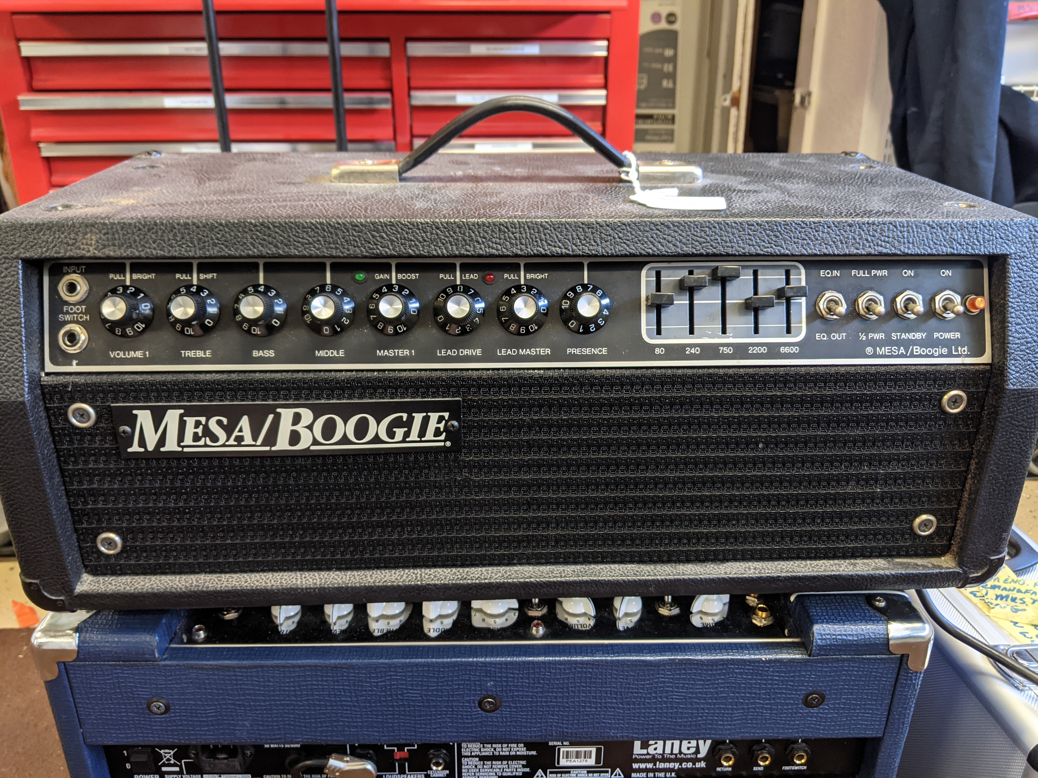
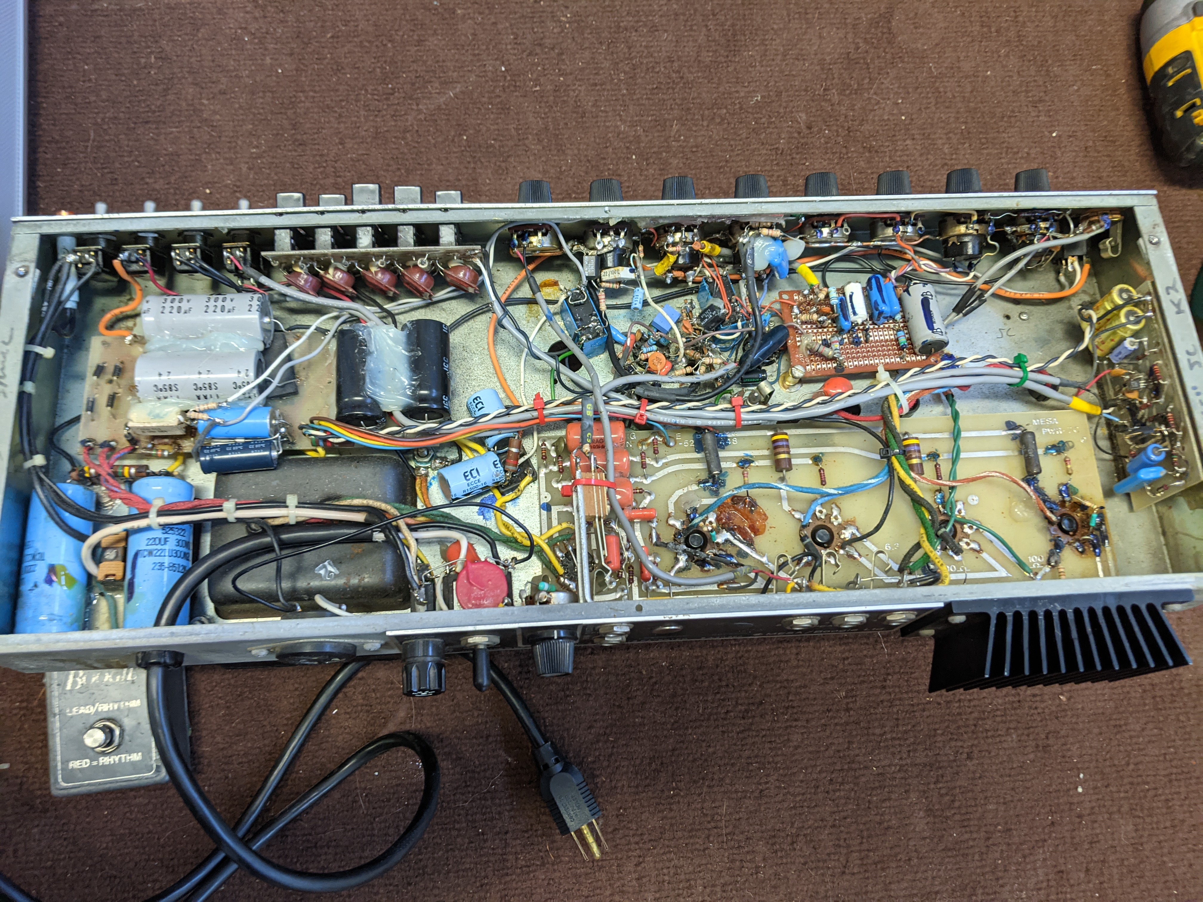
I came into possession of a Mark series amp (it's non-functional, and was purchased for parts) that I can't seem to identify. Someone before me made a complete mess of the inside (cutting up and rearranging the preamp board, etc), so I can't make heads or tails of what it should be.

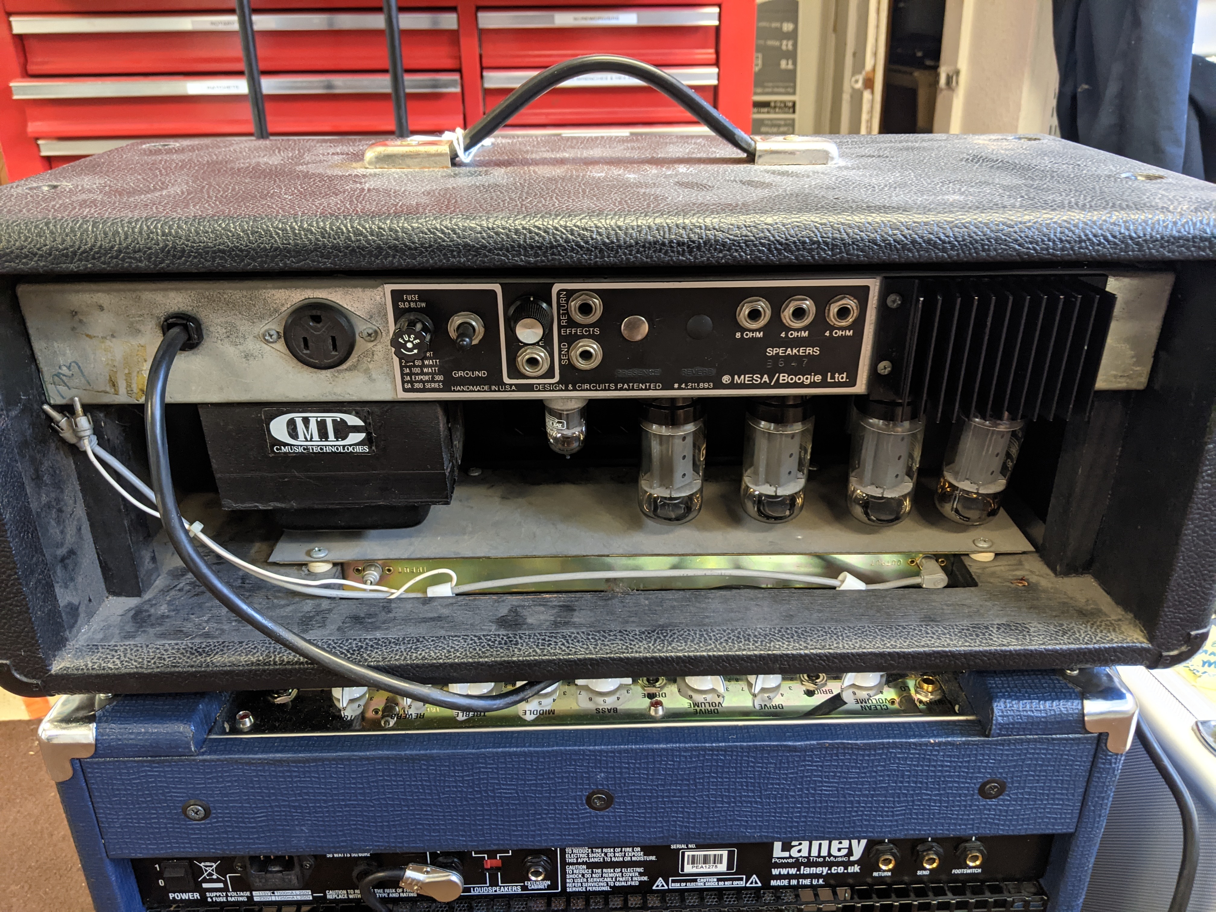
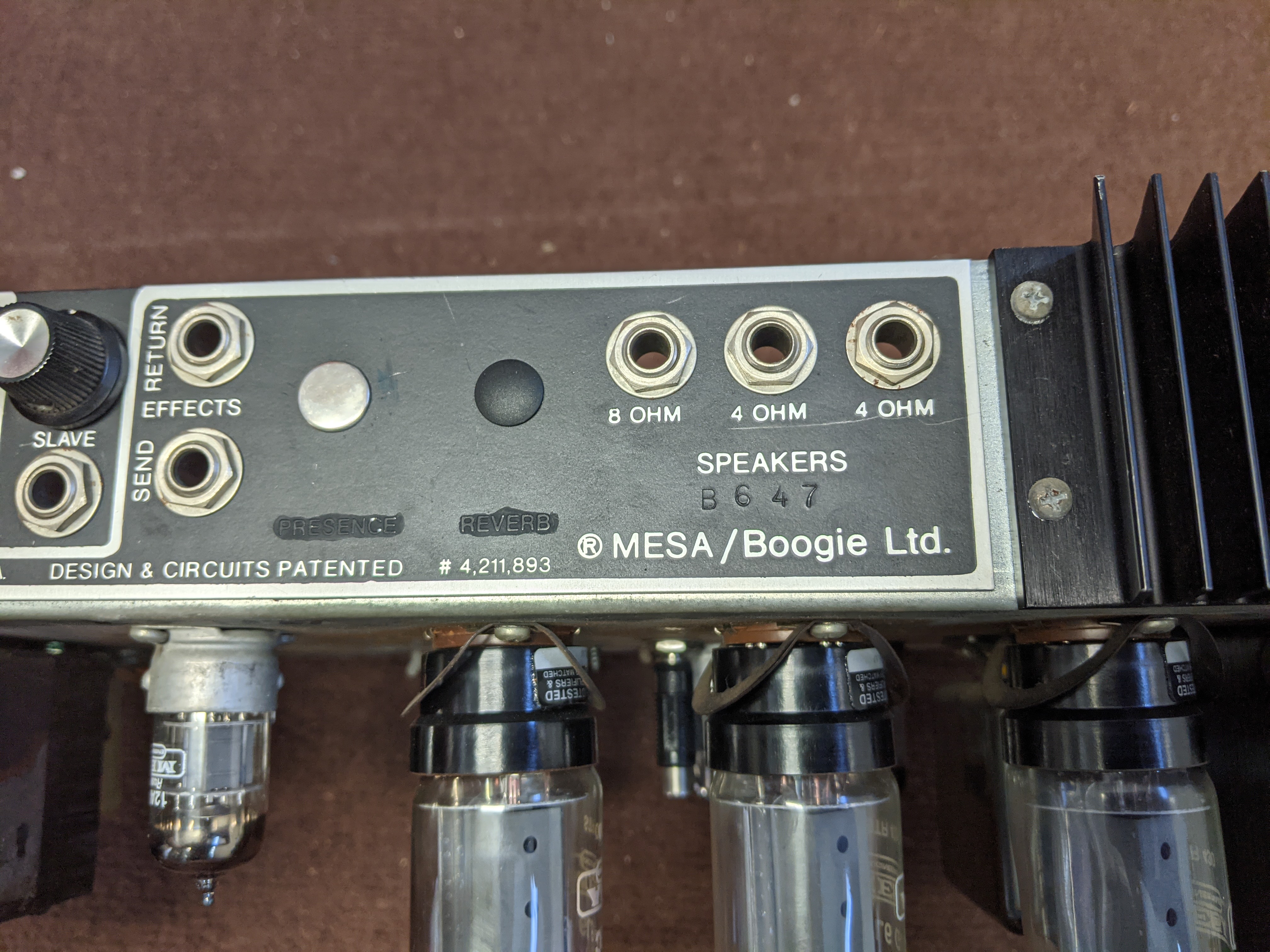
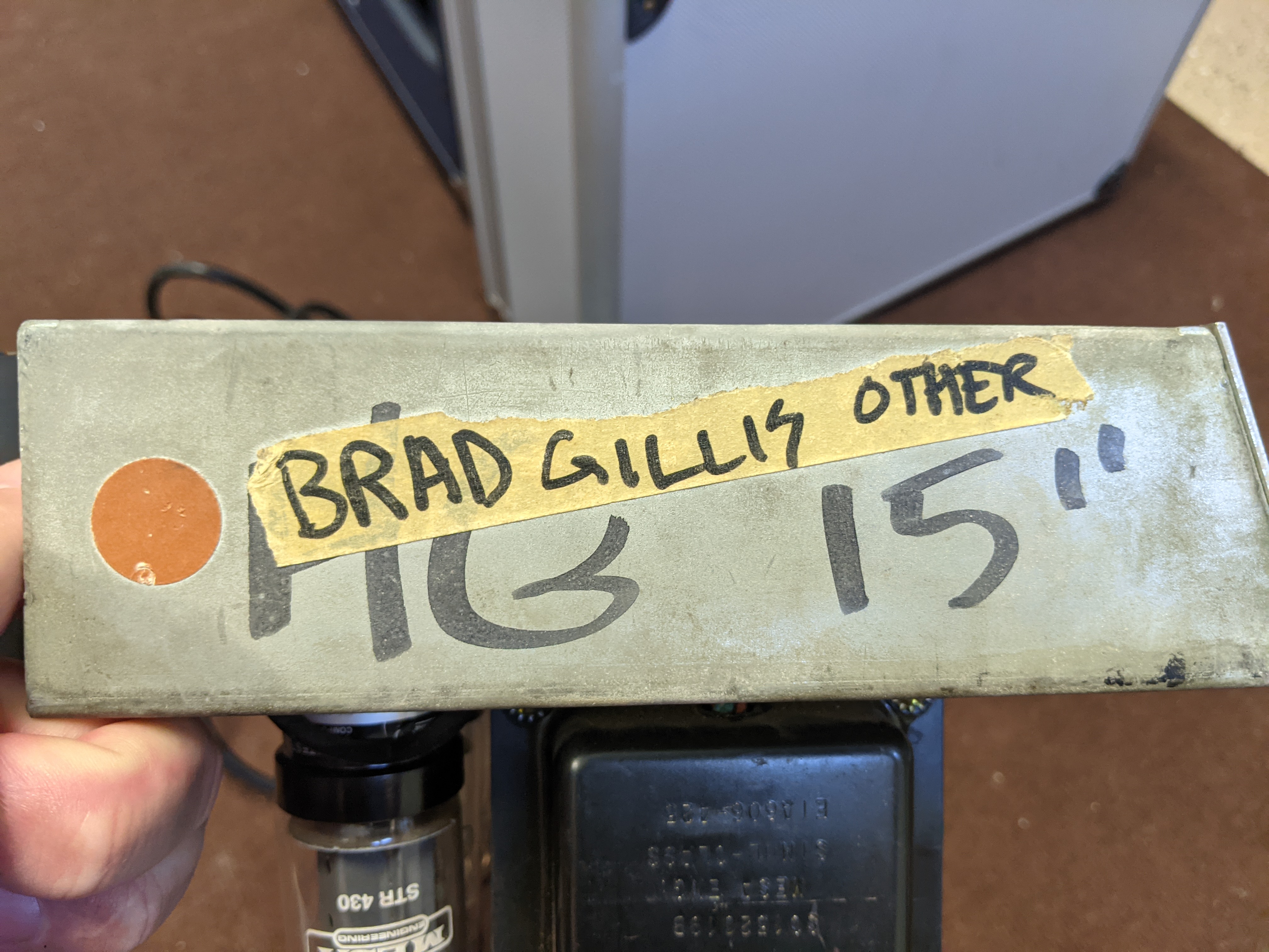
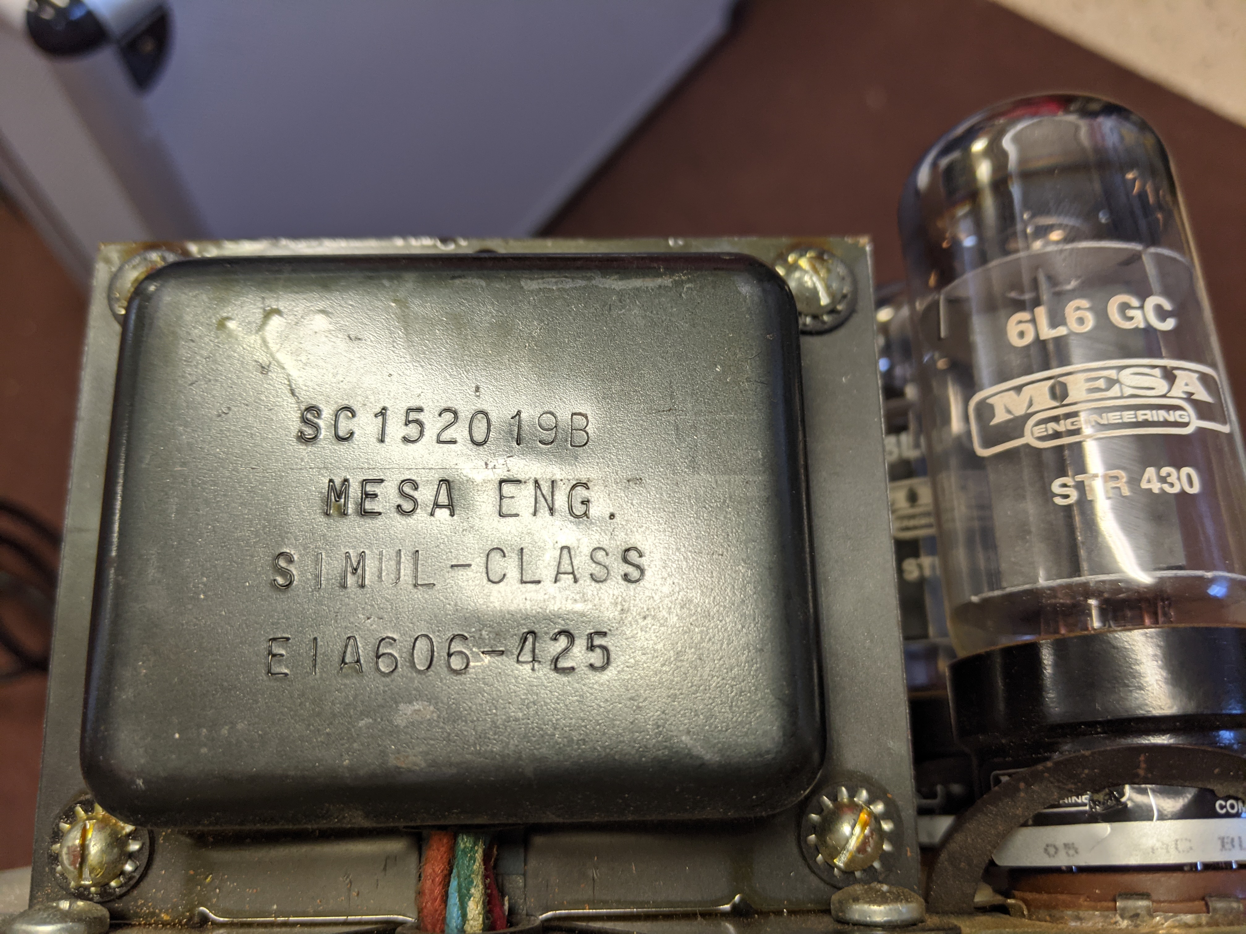
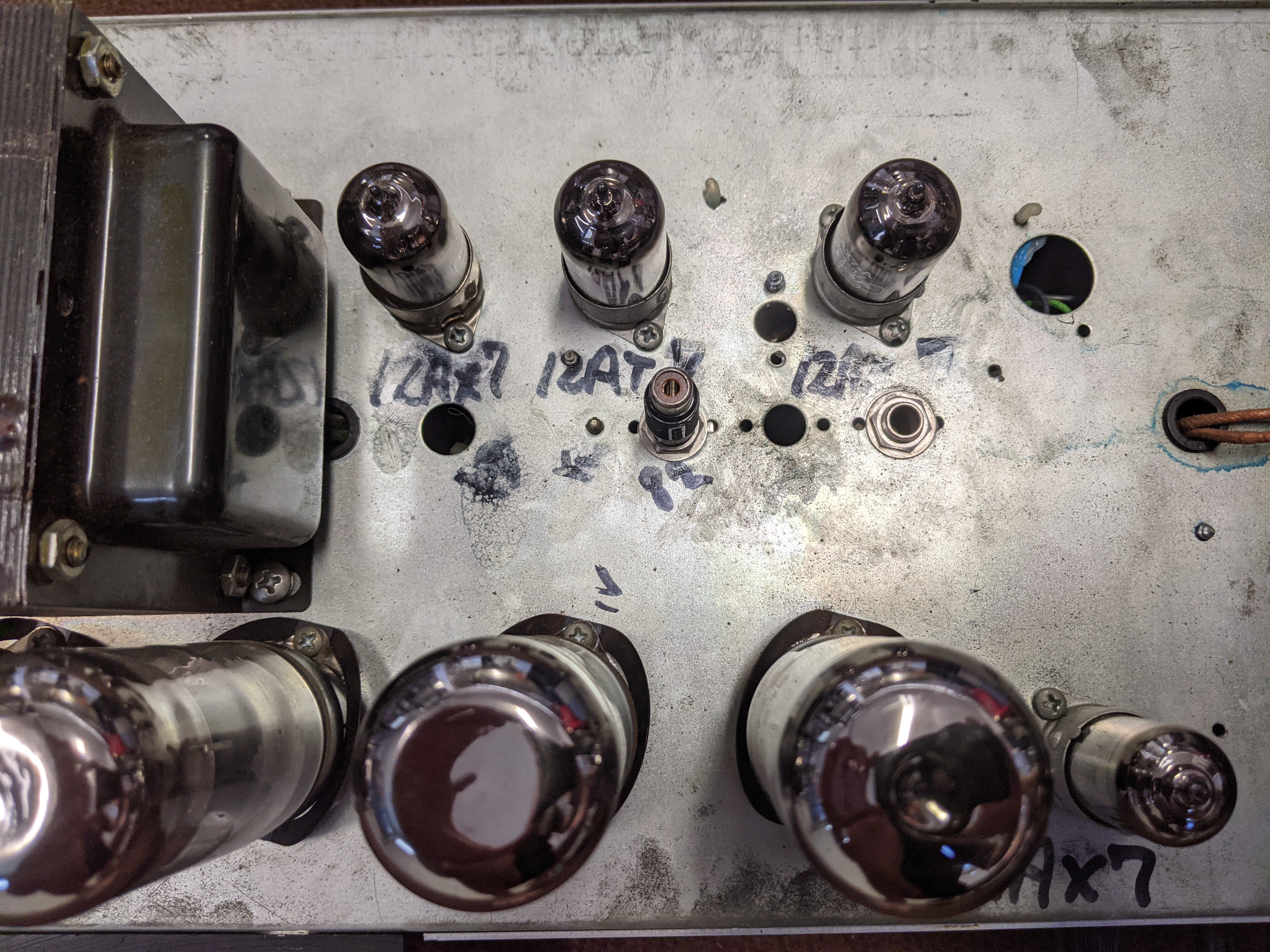
The serial number is B647, and on the side of the chassis it says "HG 15". On the top in marker it says "HG Simul". There is a piece of tape on the other side that says "Brad Gillis Other". It contains a reverb tank and a 5-band EQ, and 4 6L6 tubes. It is dual channel and has a "Gain Boost" knob. The output transformer reads PT100 Simulclass, however the switch on the front says "Full Power / Half Power". It has a presence control on the front, and space for one on the back, but it's plugged with a silver plug. There is also a reverb tank and a reverb transformer, but the hole for the reverb control is also plugged, and the left-most tube (viewed from the back) is missing (which I think should be the reverb tube). There is a signature on the back which looks like "MB" underneath the power cable.

Inside is again confusing: the output board says PWR-7C, the preamp board has been cut up and the number is missing. It seems to have a mix of relays and Vactrol's to control the channel switching. This is confusing, as I thought Vactrol's were only used in the 2C (and later). If it was originally a reverb unit, why isn't it an HRG instead of HG? The preamp board appears to have been cut into 4 separate pieces, and has relays and Vactrols glued all over it.

On balance, I would guess it's a somewhat earlier Mark 2B, and I'd like to restore it if possible. Maybe someone thought they could convert it to a 2C and got lost? Given the state it's in I don't mind gutting it completely and hand-wiring a 2C+ but I need to know where I'm starting from.

I'll upload some pictures when I get home and have it apart again.
 
Pics.

PXL_20210914_172535258.jpg

PXL_20210914_172552070.jpg

PXL_20210914_172620558.jpg

PXL_20210914_172658090.jpg

PXL_20210914_172745334.jpg

PXL_20210914_172807705.jpg

PXL_20210914_172846548.jpg
 
I don't know how much help I can be to you Matador but I'll give it a shot. On the outside, it looks like a IIB to me. (The inside is a different story!) As far as the markings go, HG 15" would mean 100/60 watt wide chassis. (The wide chassis would move either the Presence or Reverb to the front panel, depending on how the amp was spec'd.) I don't believe Mesa had a different front panel to distinguish 100/60 from Simul-Class/Class A. So the Full and 1/2 power labels would be the same. The MB initials are Mike Bendinelli. He tested most of the amps in those days, is still at Mesa/Boogie, and actually recently finished some maintenance and mods on my MkIII!
To me, it looks like this amp probably started out as a 100/60 watt with Graphic EQ. At some point, it was converted to Simul-Class, and was perhaps in the process of having Reverb added. I don't know what else is going on under the hood, but some of it doesn't look very pretty! :shock:
 
Thanks, I think everything you wrote is spot on!

I did manage to get through to Mesa service, and they said that according to their records, it left their factory in late 1982 as a non-reverb, Mark 2B 15" combo amp. Given the markings it was probably built for Brad Gillis, a signature artist for them (at least at the time). They think the conversion to Simul-class was likely done at the factory (along with modifications to make a 2B+). This was something that was commonly done leading up to the 2B to 2C transition. They think the head shell, based on the shape, is actually from a Reverb-equipped Mark 3 (but may also be a 2C+ shell, which at the time was visually identical). Those were the shells that were used to convert 15" combos into head units (again, at the time). Apparently the 1982 to 1983 time frame saw a lot of changes and a lot of "custom" work, so to some extent all bets are off.
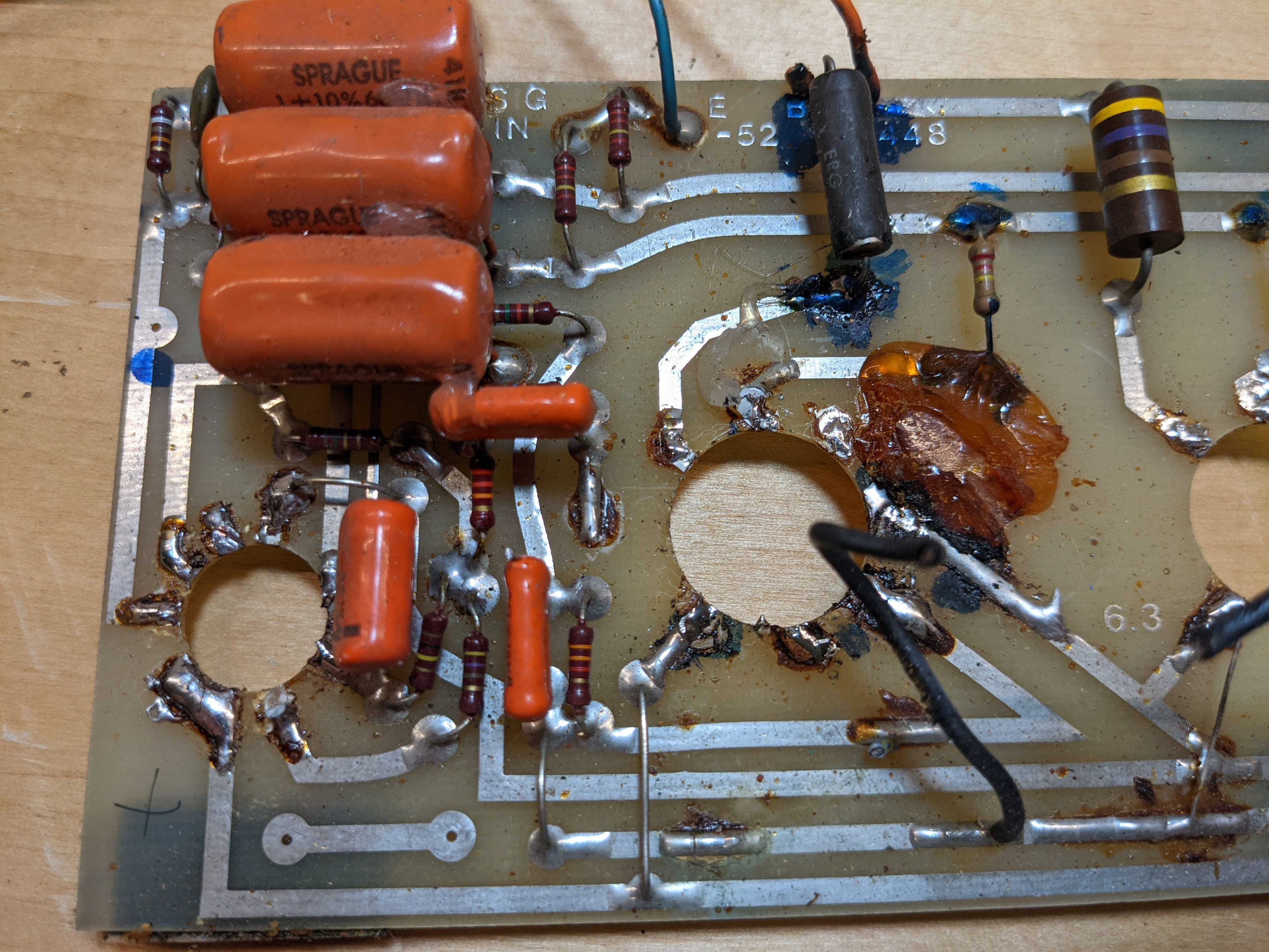
Based on the fact that there are 5 Vactrols in the mess of wiring and components, I'm guessing the sequence was something like this: 1982 it was a combo amp. Sometime in the '82 to '83 timeframe Brad had it converted into a head and had the Simul-class conversion done. Sometime in the early 90's, someone attempted to convert the circuit into a 2C+ with Reverb (which I think would be a DRG 15"). Given the original RP9A board that would have been in this amp isn't easy to convert, they ripped it out and did it point-to-point, but it's a mess of components and silicon glue and it's incredibly difficult to trace the circuit. Based on a quick visual inspection, the 'return' jack definitely leads to the final preamp tube grid, which means this can't be a 2B circuit anymore, and looks similar to the 2C+, so this matches. Someone also added a set of relays to add two LED's to the front panel (one green and one red), which show you which channel is currently active, which is something I actually like.

I think my plan is to completely gut it, refinish the chassis, and install a complete 2C+ circuit with my own PCB's.
 
Wow, this hurts to look at!

I'm not totally sure, but what you mentioned about the return jack leading to the final preamp tube grid might actually be present in Mike B's "loop mod" ("IIb+").

Good luck with this project! The original transformers are magic, so there are undoubtedly some killer tones to be had!
 
Ok, I decided to gut this thing and see what I can do with it.

I've serviced many Mesa amps, and there are a lot of things that bug me with the design that I want to rectify. Since I have to start from scratch with nothing but the output transformer, power transformer, and EQ inductors, I have a clean slate. I've wanted to do this for years but none of my customers wanted to risk their own vintage amps, so I'll take the plunge with my own.

1) I don't like the fact that the power board doesn't utilize any of the vertical space available, nor does it use the area to the left of the power transformer. This crowds the center of the amp and pushes the EQ amp over to the other side, leaving wire bundles that have to travel back and forth. I'll redo the PSU to utilize this space to free up the center of the chassis.

2) I will convert the PSU to a regulated screen supply, fixed to 450V, with the rest of the downstream supplies tapped from it. So B will be 450V, then C will be 440V, D will be 430V, and E will be 425V. This is only slightly different from stock. This should greatly reduce the noise and hum susceptibility. It will get a new PCB of my own design. It will support adjustable bias and bias balancing.

3) I will add a heater elevation circuit (adjustable in the 40V to 80V range) to further reduce noise.

4) I will switch the tube quad from 6L6 to 7581A tubes, with a provision to run EL34's in the outermost Simulclass tube pair.

5) I will move the EQ amplifier back over to be located in front of the EQ faders (where I always thought it should go). It will get a new PCB of my own design.

6) The preamp and power amp boards will need to be redone with custom PCB's. I've always HATED the build style which bent over the socket pins and soldered directly to the PCB's, because it makes them damn-near unserviceable without a lot of painful rework. I will use hole cutouts in the boards and run flying leads up and through to the PCB's, so that they can be easily disconnected and serviced. I like high voltage locking plugs used in industrial supplies so the tubes can be disconnected easily from the PCB for servicing.

7) I will reconfigure the back panel: I will move the EQ and Reverb footswitches to the back panel, on separate jacks, so they will work with the newer Mesa footswitches. I'll ditch the fuse holder for an integrated IEC-style plug with built in fuse so that you can use pluggable AC cords (like every other modern amp uses). I'll ditch the ground capacitor, and use those two holes for the EQ and Reverb footswitch jacks. I'll add the Reverb pot where it would have been from the factory.

8 ) All of the channel switching, EQ and Reverb control, and control of the Vactrol's will be done by microprocessor.

9) I will add a biasing monitoring circuit, which displays to a small 1" OLED on the back panel. It monitors the plate voltages, bias voltages, and calculates the static dissipation, and shows the state of channels and functions. The bias monitoring circuit means you can swap in new tubes, and just turn the bias pot until the display says the tubes are idling at the correct levels, and indicates if a tube is bad or going out-of-spec.

It will be the most modern and high-tech Mark 2C+ on the planet. :lol:
 
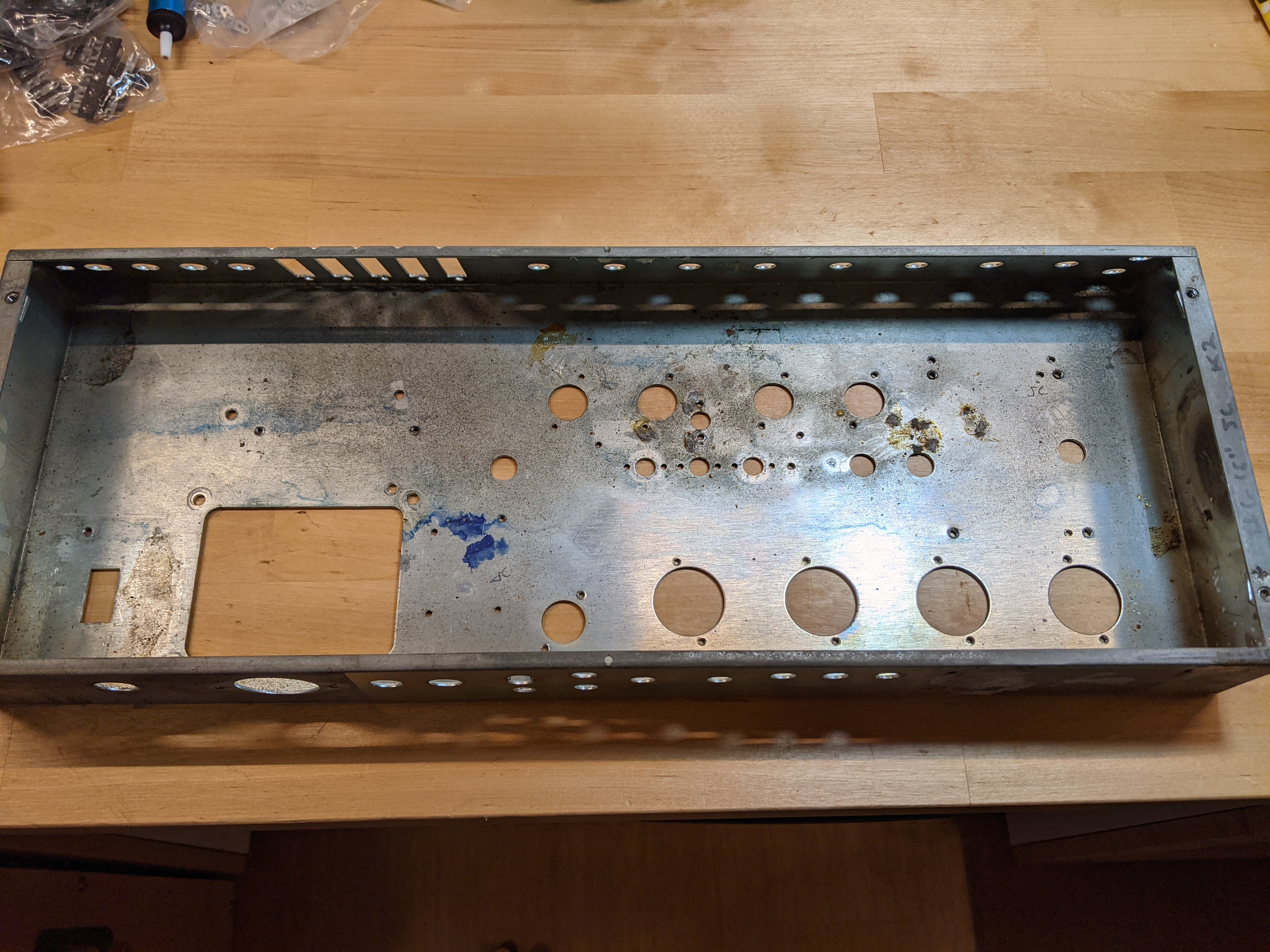
chassis_bottom.jpg

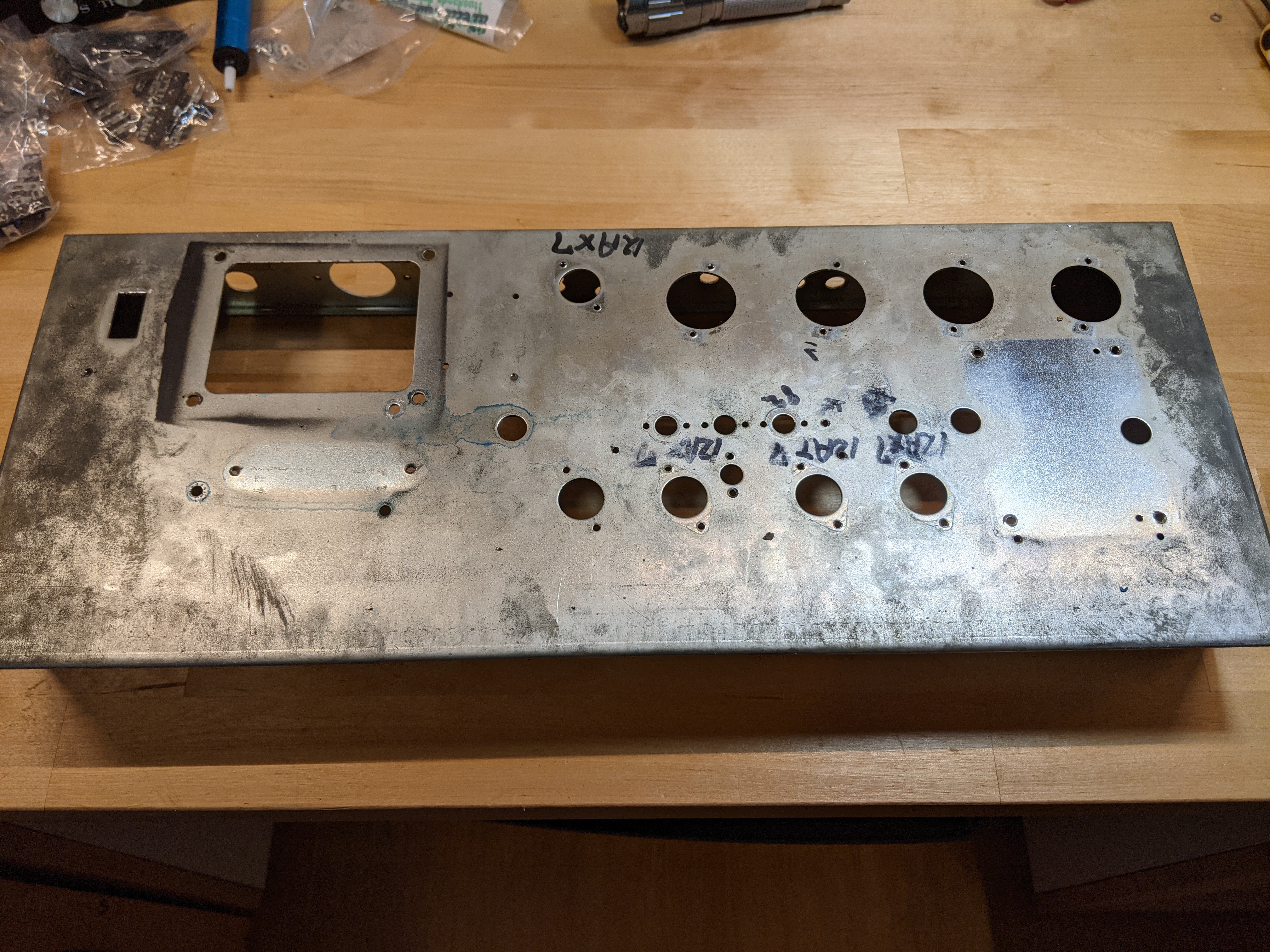
chassis_top.jpg


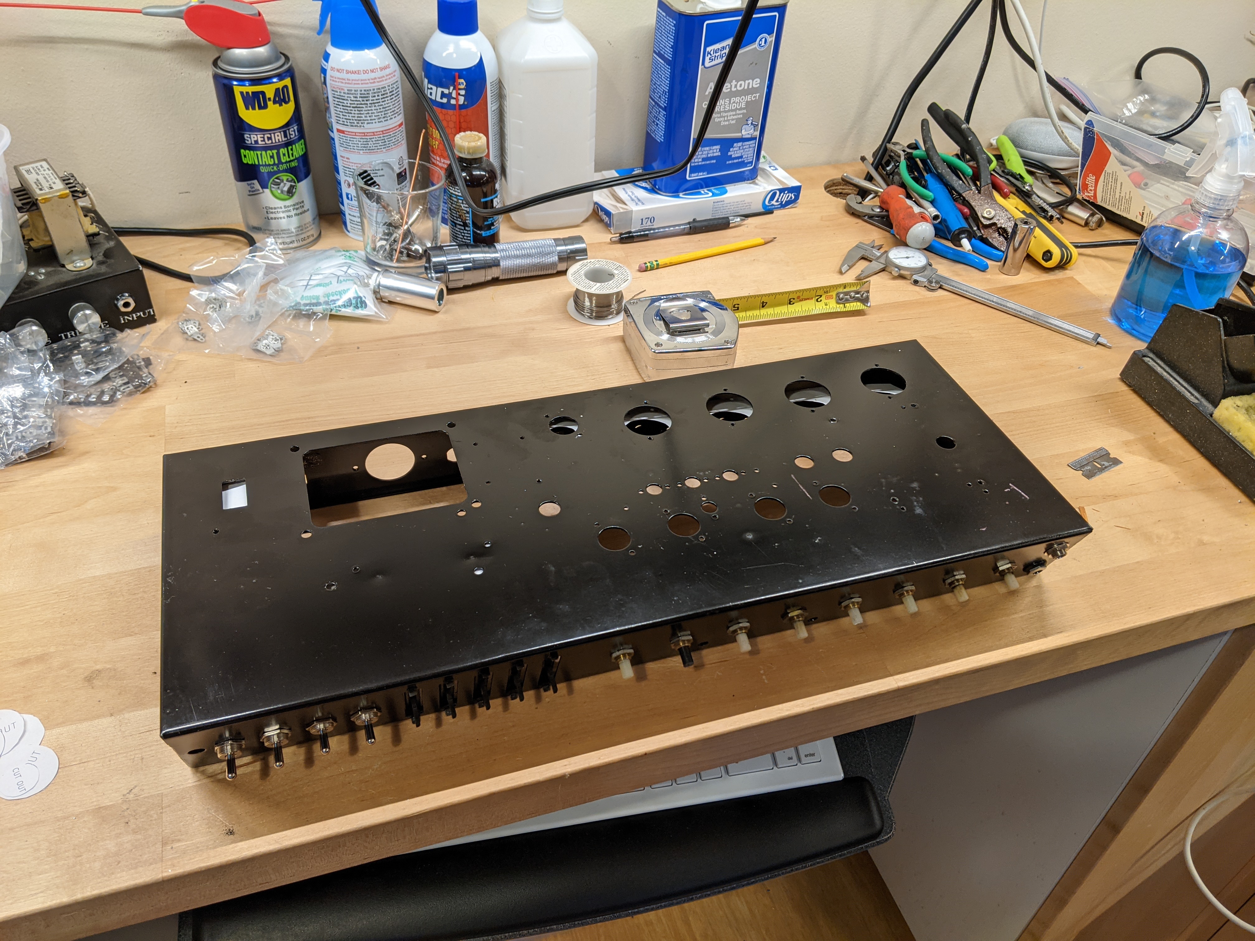
First is gutting and refinishing the chassis. After stripping everything out, I belt sanded the top and bottom to fresh bare metal, primed with etching primer, and painted a base coat of black enamel. I was careful to mask over and retain all of the original writing from the Mesa folks on the sides, and I kept MB's signature as well. I'll repaint and clear coat the top once I'm done cutting any new holes.

chassis_refinished.jpg


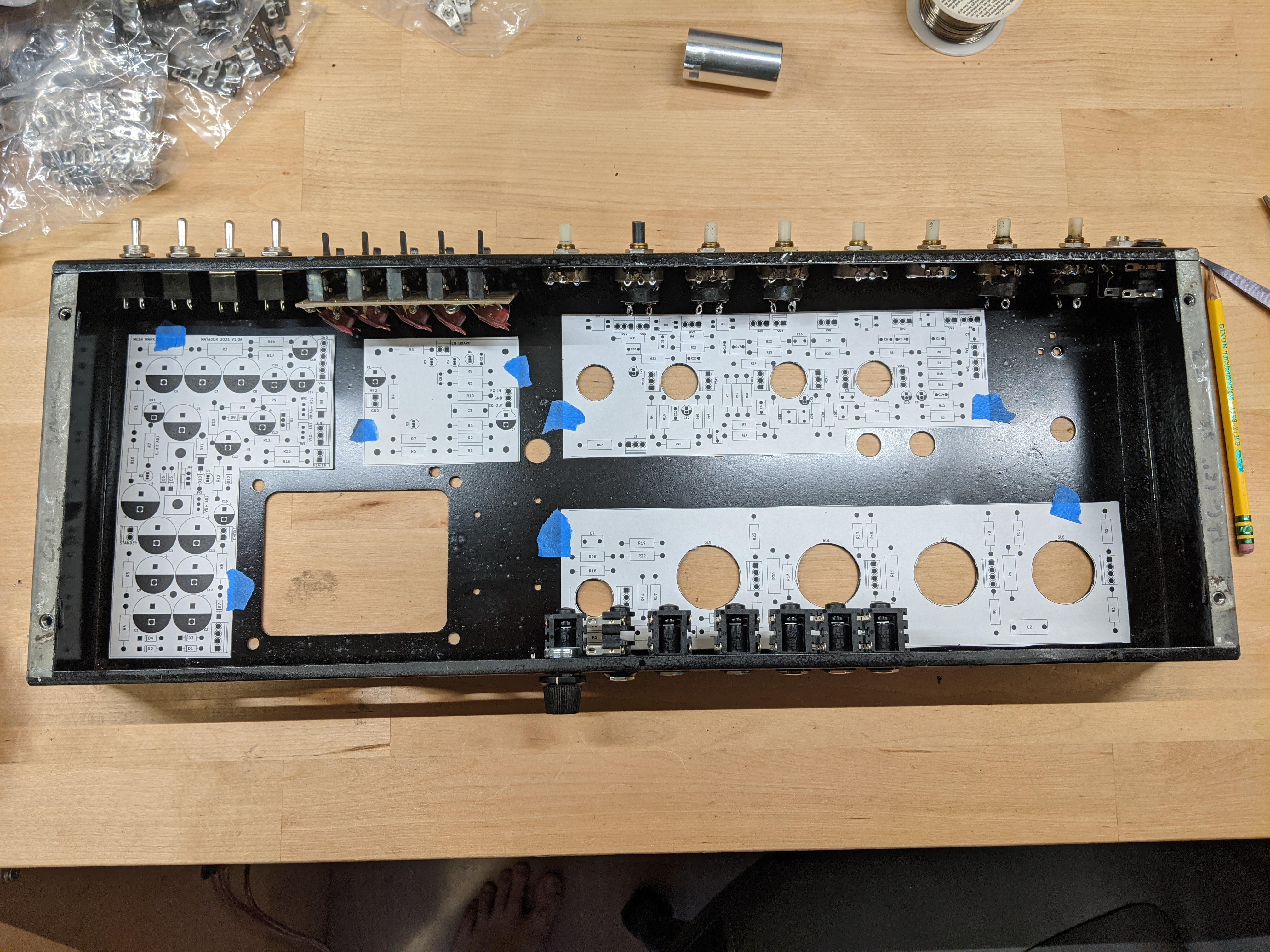
I removed all pots and jacks, replaced all of the switches, cleaned and lubed all the pots, and replaced all of the jacks with Reans jacks. I printed the new PCB's on paper to test fit and show the overall layout. There will be 6 PCB's, and the microcontroller will be placed where the EQ used to sit on the right side of the chassis.

chassis_layout.jpg


Now I wait for parts to arrive.
 
hello
great job man ...cool.
offering a bias setting and separating the capacitors and tubes from the rest is a great idea.
a question ? you made the pcb yourself? you made and placed all the components?
I am interested myself in replacing my PCBs on my MARK2B ...so it would be possible to reuse your PCB implementations so that I can achieve the same ones?
your modifications are very importante and it will be a dream to realize a same here...
thanks for your answer...
dom
 
hello again
you can see in my pict ,one of the transformation :
i put a pluggable AC cords.
really cool because you can unplugg very easily without 3 meters dragged on floor.

thanxs
https://imgur.com/gallery/BD7O43S
 
domglop78 said:
a question ? you made the pcb yourself? you made and placed all the components?
I am interested myself in replacing my PCBs on my MARK2B ...so it would be possible to reuse your PCB implementations so that I can achieve the same ones?
Yes, they are entirely my own design, but based on tracing the circuit of the Mark 2C+ (and information available here in the forum). Keep in mind the circuit is different between 2B and 2C+. There is no shared layout / organization between my boards and Mesa's boards (in fact, my boards are quite a bit smaller, because I can utilize a full two sides for routing which means I can pack the components much closer together than Mesa could using their 1-layer designs).

I'm basing the layout on the wide (15") chassis, so whether or not it will fit in another depends on the dimensions. Do you have a detailed drawing of the internal layout you are using? I'm not planning on providing/selling boards to anyone but would be glad to post PDF's / Gerber if you want to purchase your own.
 
OK
I can see that each person works solo for their achievements. repair or build your amp remains a secret thing here but then a question: why publish articles and photos to say afterwards: I simply realize them for myself. Lol it's a joke !! all kind of musical forum will help people to engage a good understand or to repare.... here you might as well not publish anything except for complacency !! without no solidarity in this forum I will realize my pcb myself (I will take the time) and I will publish them to help people who want to repair or create their amp.
Note: if i had more money, i will buy a new mesa-boogie but it's not ..... thx for the solidarity of the forum , i think i will don't reply no more.
so long.
 
?

I literally have nothing to share at this point other than a set of paper outlines with some preliminary component placements, that haven't even been routed yet. I already said I would release the PDF's once I actually have a set of boards that I know works. In case it wasn't clear, I just started this project a few weeks ago, and it's a work in progress.

If you want detailed drawings of my paper outlines I would be happy to send them to you.
 
domglop78 said:
OK
I can see that each person works solo for their achievements. repair or build your amp remains a secret thing here but then a question: why publish articles and photos to say afterwards: I simply realize them for myself. Lol it's a joke !!


I'll tell you why. I used to be very active on number of electronic related forums, sharing my work and research freely only to be ****** later. To this day I see my projects posted online in sell sections or ebay (I secretaly marking my work), some of it ended up in comertial products claiming years of research.

That is the reason I stopped. As much as I would kill for a scan of Mark series original PCB or to have access to one for a day I won't blame anyone for not giving me this opportunity on my chosen time. But I know the time will come.

My advice? Want stuff, info, product? Do your own homework
 
hello and thank you for your feedback.
I understand your opinion and I understand you when you see your work being sold by unscrupulous people ...
for me a forum is used to exchange information and offer various solutions for troubleshooting.
the fact that it is no longer possible to buy Mesa cards remains a problem.
I will never endorse the fact of selling a Mesa copyright as a series, but i think it is just to offer manually and individually help on the realization of a functional unit just to have a great amp for the music.
best regards
dom
 
hi
For all people who will want to change the Chassis look at: https://www.tube-town.net/
you can find a germany shop who you can buy an aluminium chassis for Mesa Type Mark.

TT CHASSIS 021 : Mesa Short Style Chassis, bare Without drills and cutouts
Aluminium Chassis Mesa Width Style
Size: 523 x 233 / 212 x 60 mm
Material: 2 mm Aluminium (AlMg3)
40€

TT CHASSIS 068 : Mesa Short Style Chassis, bare Without drills and cutouts
Aluminium Chassis Mesa Width Style
Size : 432 x 216 x 60 mm
Material: 2 mm Aluminium
Protectionfoil Outside
30€

This is an information to help all people with a bad chassis MB Amp ....
best Regards
dom
 
ANYWAY.... :roll:

Back to the OP's idea, this is awesome. I'd love to see a reworked IIC+ brought into the modern age and done properly.
Very keen to see how this develops!
 
It's shocking how difficult it is to get parts these days.

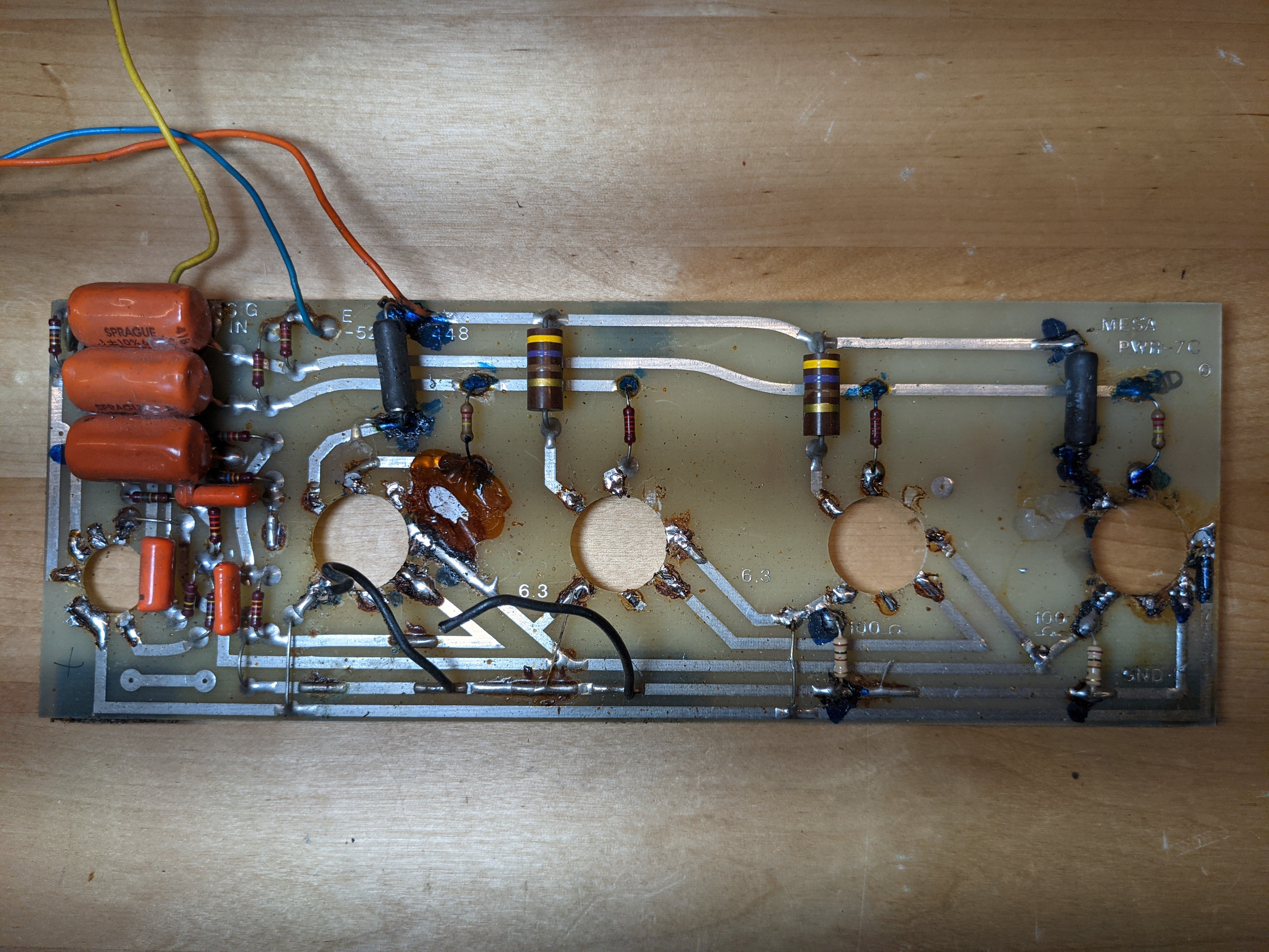
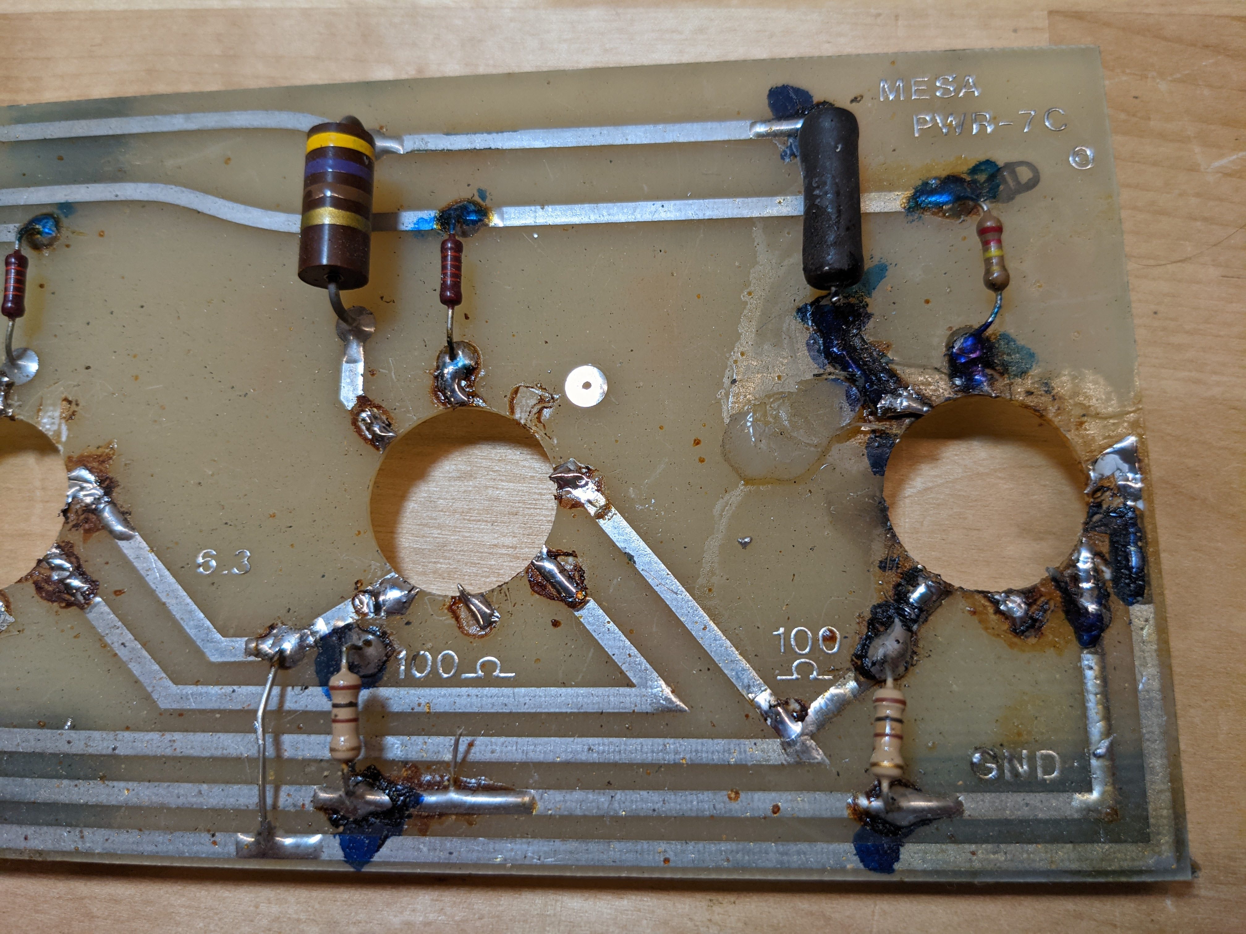
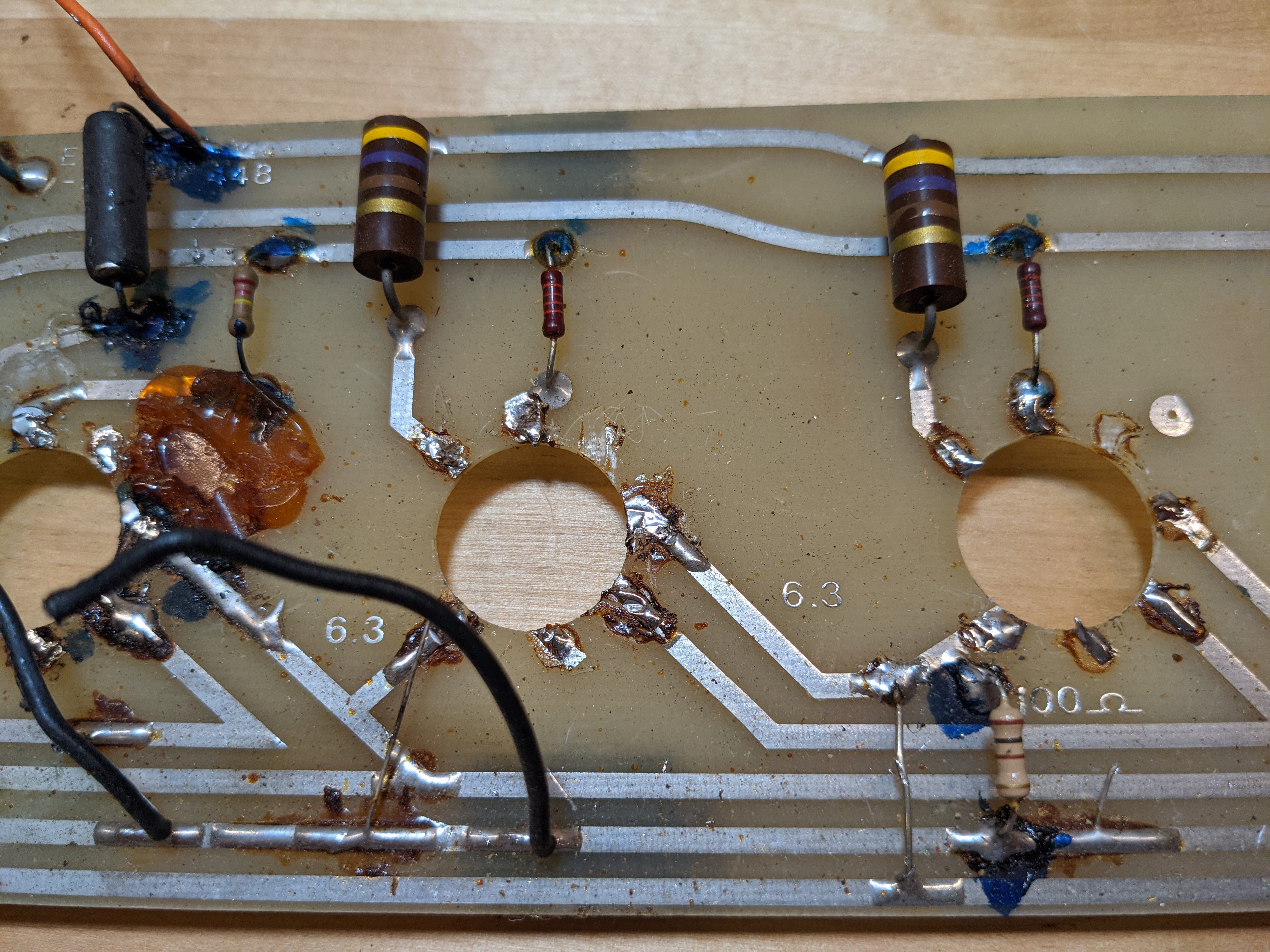
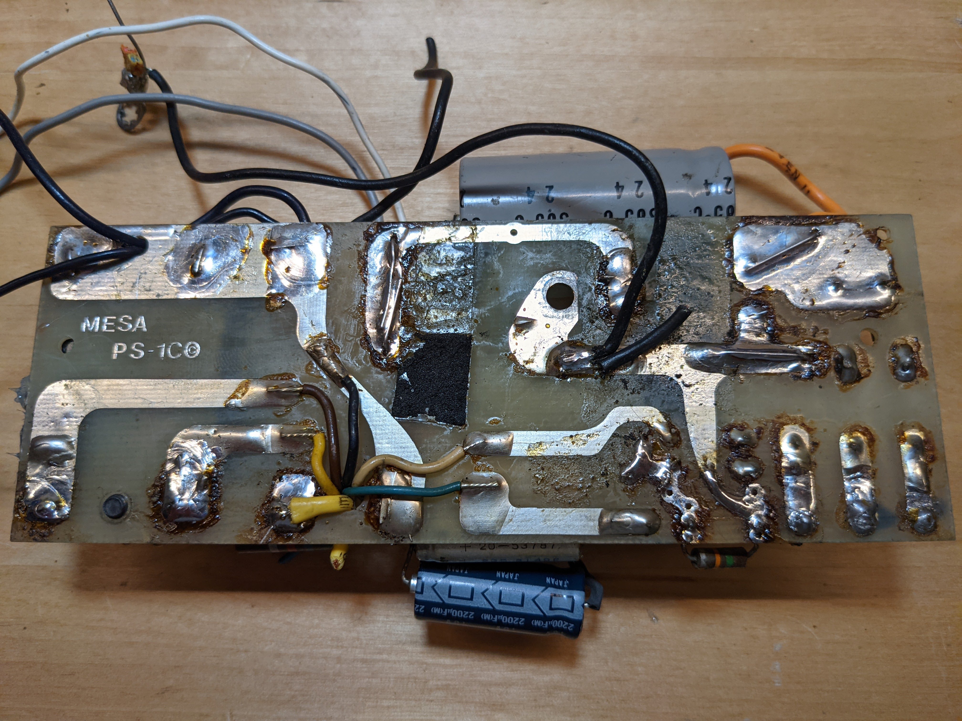
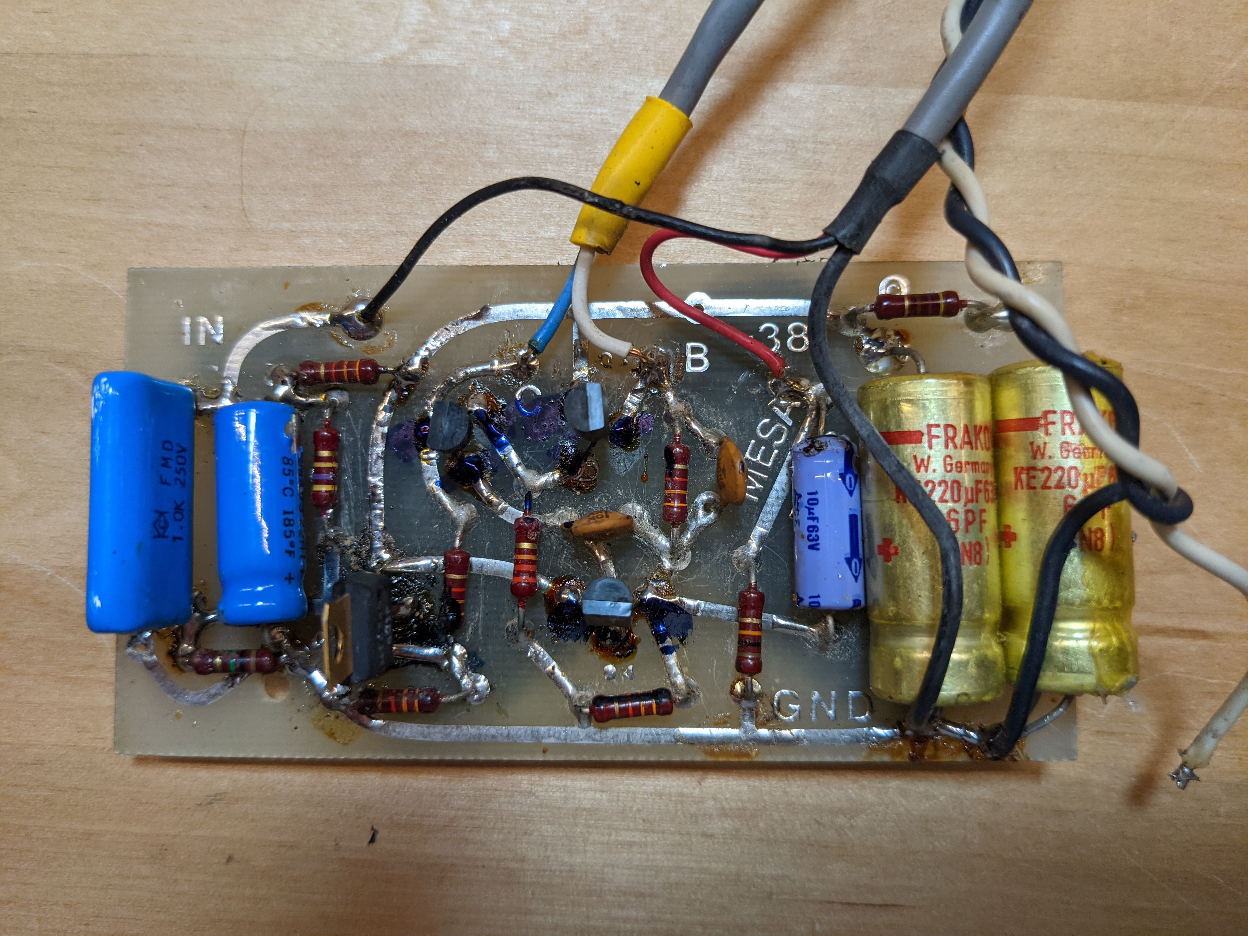
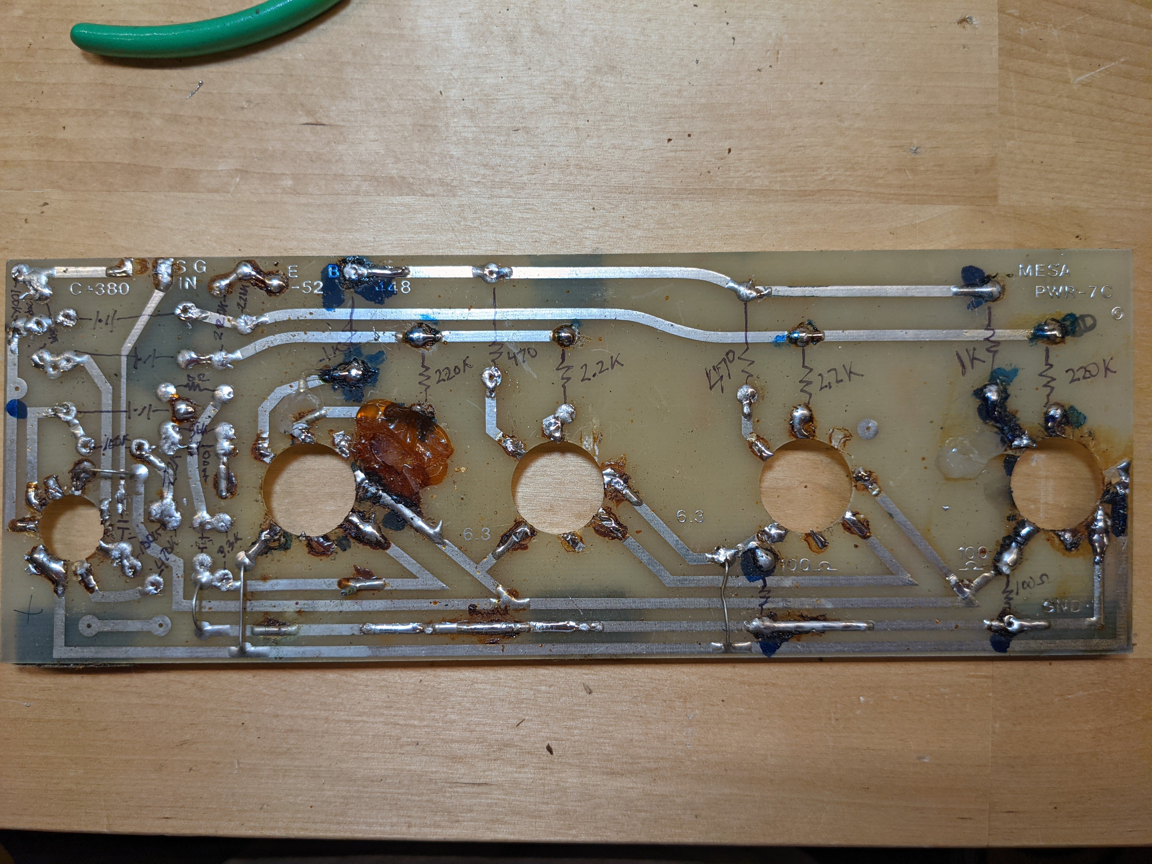
Here are some images I took of (what was left) of the original boards. These are the PSU, EQ, and power amp circuit boards. I won't throw them away until I'm done in case anyone wants any other pictures of them.

PXL_20210928_181802057.jpg

PXL_20210928_181919125.jpg

PXL_20210928_181923381.jpg

PXL_20210928_181928169.jpg

PXL_20210928_185130495.jpg

PXL_20210928_185931937.jpg

PXL_20210928_190023353.jpg
 
If you haven't refinished the chassis yet, consider that you can have it chemically stripped to bare steel and then regalvanized, and then chromated if you want. This will REALLY bring it back to like new. I've done this on a few "basket case" Marshall chassis.

It doesn't cost that much to do it, in fact it cost me just 75 bucks to have a Marshall JMP 100 watt chassis stripped, galvanized, and yellow Zinc Chromated. Any sheet metal shop in your area can put you in touch with a shop that can do that for you.
 
I finally made a bit more progress.

Someone offered to purchase the amp from me provided I could restore it as original as possible. So my tact has changed somewhat, given I still want to fold in everything I've learned repairing these amps for the past 20 years.

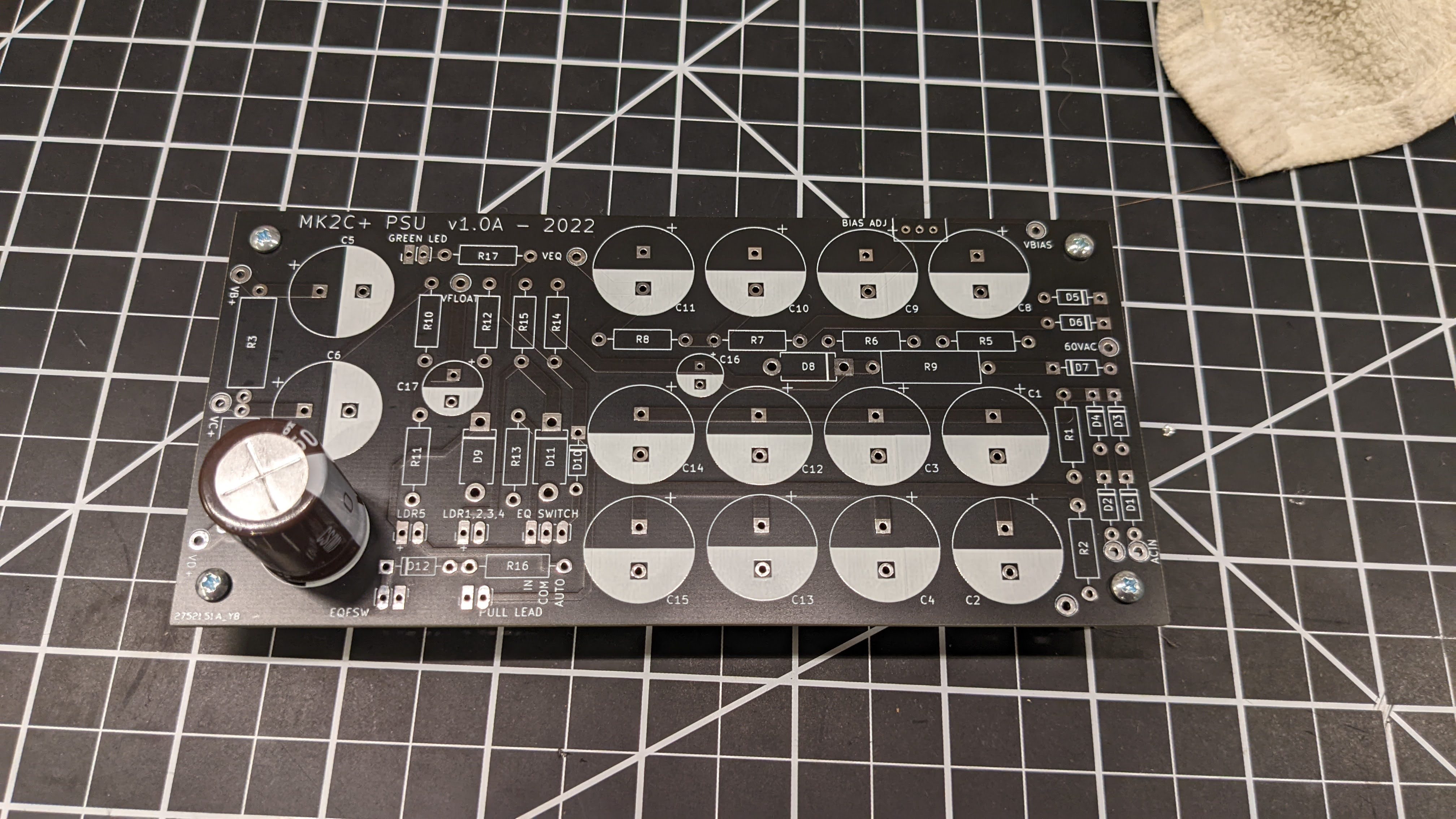
Here is the new PSU board: this has undergone the most changes from the stock circuit (although the size is identical and the layout is similar):

  1. High quality axial caps are getting harder and harder to find. Good, compact, high temp, high reliability radial caps however are much easier and far less costly. So I changed the layout to accommodate compact radial caps, which better uses the vertical space in the chassis. It also means I can generally add more filtering in the same volume as the stock circuit.
  2. I added a bias voltage adjustment, multi-turn pot (I get this is anti-Mesa, but there's no excuse from my point of view not to include these).
  3. I moved all of the channel switching circuitry to the PSU PCB. I never liked that the switching networks, caps, and diodes were mixed into the preamp PCB. So this is all on the PSU PCB now, with only the two LDR leads coming from the PSU PCB to the preamp board.
  4. There is a new filtered, resistive voltage divider to supply 50V for heater elevation (makes a HUGE difference on background hum, especially in lead mode).
  5. Heater 100 ohms virtual center tap resistors are moved from the power amp board to the PSU board.
  6. The Pull Lead, EQ front panel switch, and EQ/Lead footswitches all connect to the PSU PCB now.
  7. Stock diodes, resistors, and caps are still generally in the same place as the stock PCB.
  8. There is a new resistor to support front-panel LED's to visually show which channel is engaged (green for rhythm, red for lead).
  9. All connections to the PCB can be on pluggable 0.1" headers, to make repairs/swapping much simpler.

Picture of new board:
psu_pcb.jpg
 

Latest posts

Back
Top