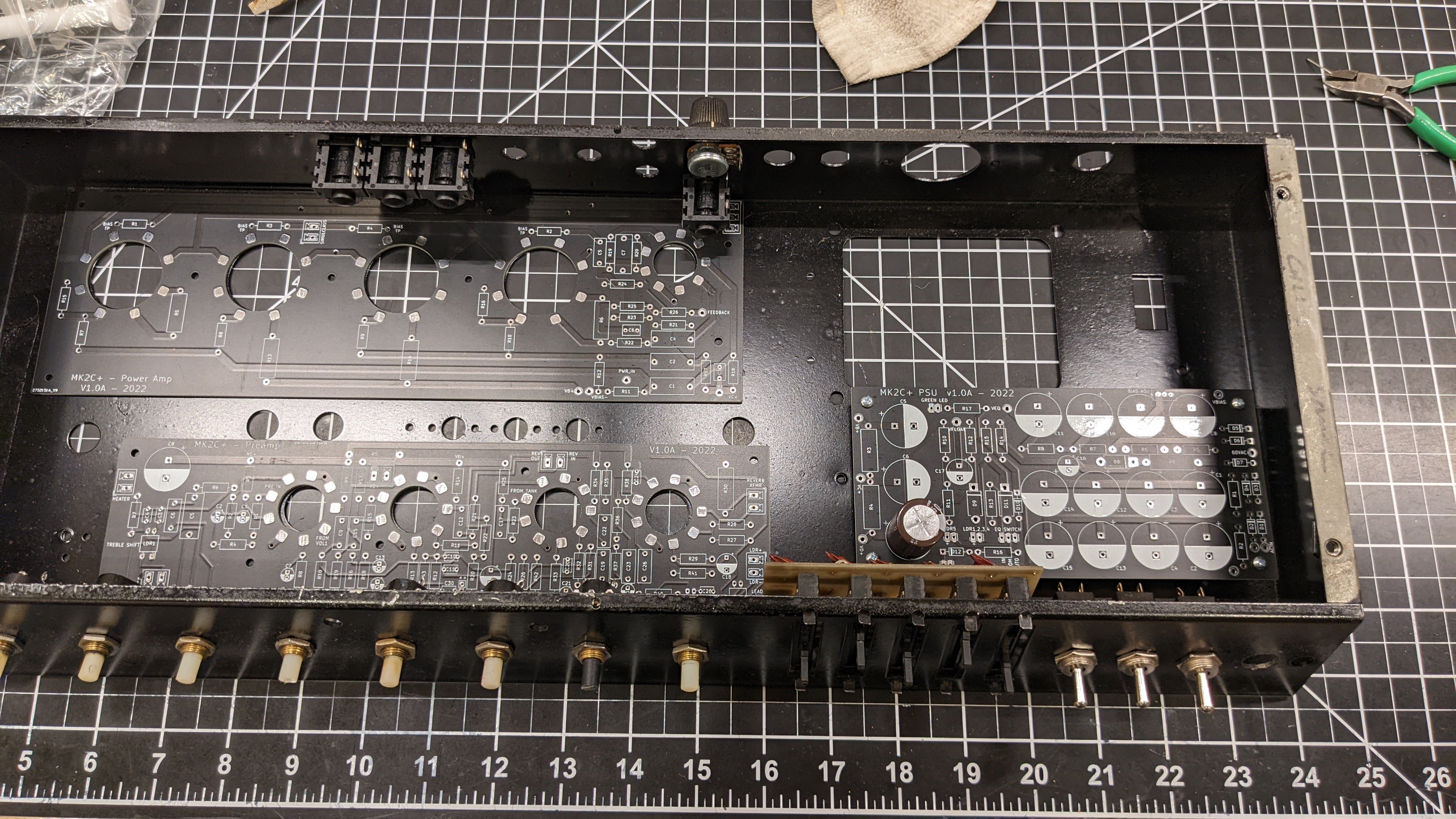
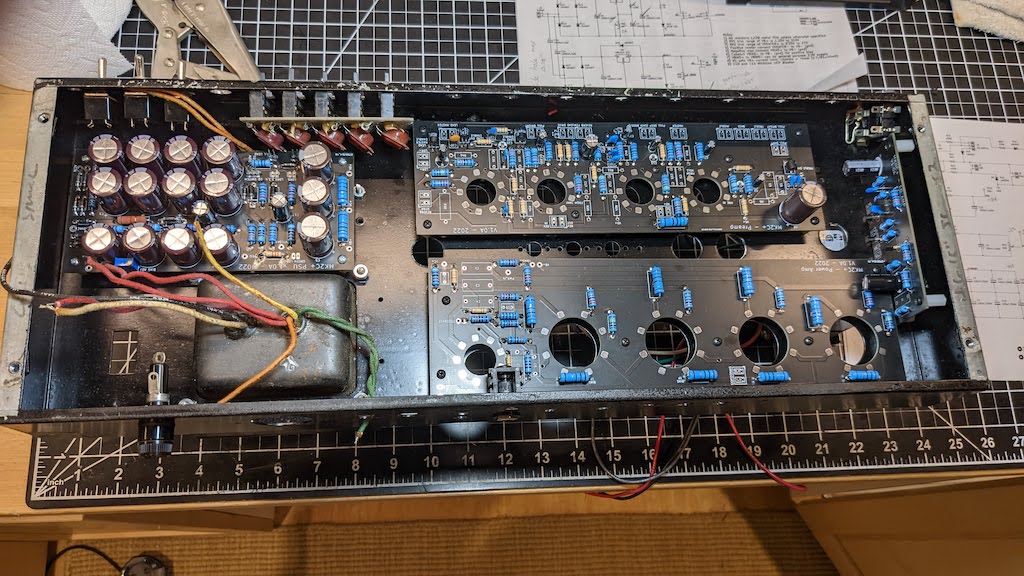
Next is the power amp PCB. Since I had the original PWR-7C board de-populated I could follow close(r) the stock component positions, except with (of course!) my own improvements:
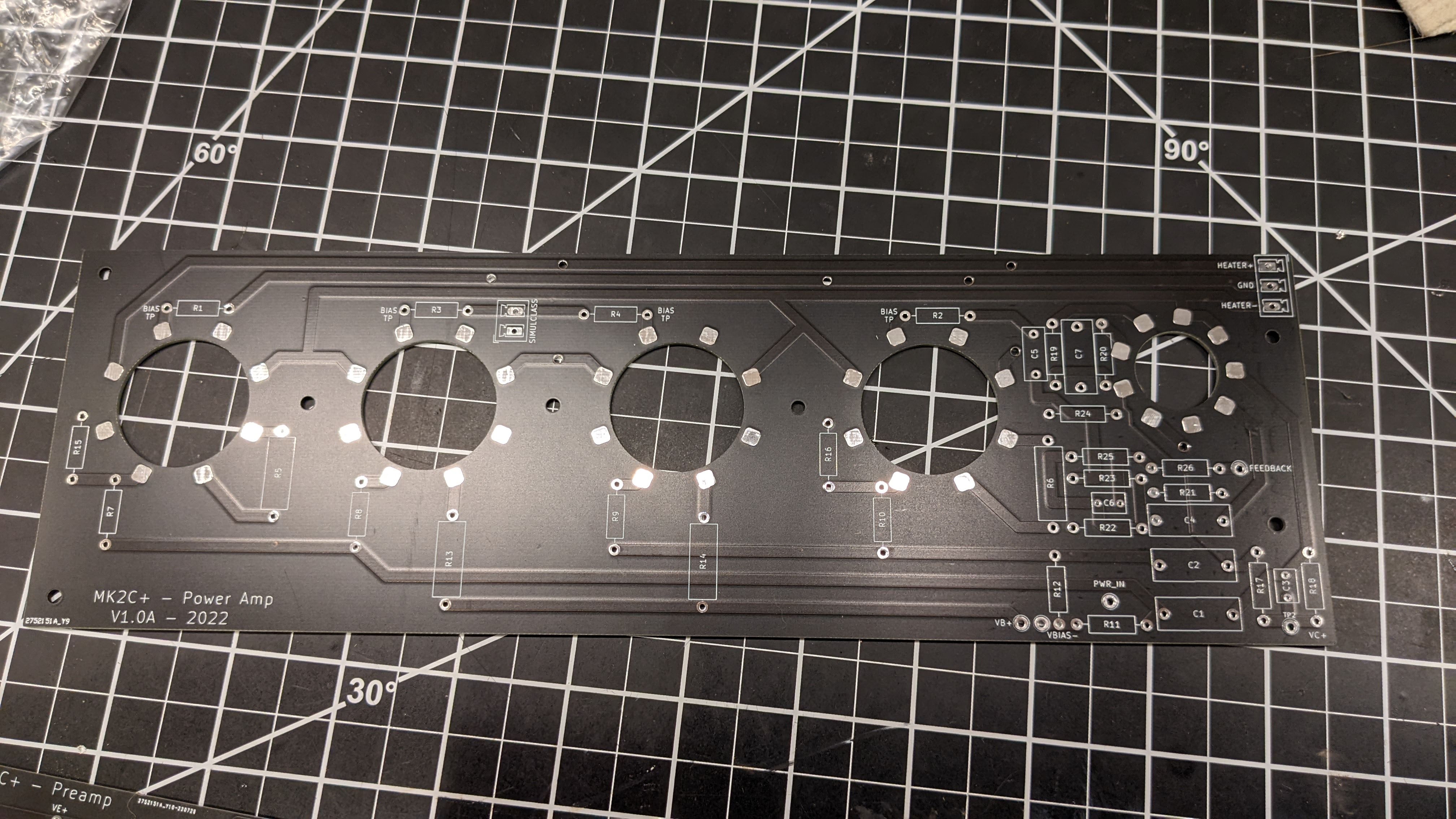
- NO DIRECT SOCKET SOLDERING TO THE BOARD. This is the most common failure mode on these amps, which is either a) a cracked socket, b) a broken socket pin, c) a lifted trace, or d) heat damage from the output tube to the PCB. Sockets will join to the board through short wire jumpers to mechanically decouple the sockets from the PCB. PCB is spaced 0.5" away from the chassis.
- 1 ohm cathode resistors are added to all 4 output tubes to facilitate biasing/balancing.
- Added more horizontal space so components don't need to be under other components.
- Screen resistor layouts are increased to accommodate 3W resistors.
- These are two layer boards, so no wire jumpers needed (jumpers are on the bottom layer now).


