Differences between IIC and IIC+

The Boogie Board

Help Support The Boogie Board:

This site may earn a commission from merchant affiliate links, including eBay, Amazon, and others.

chipaudette

Well-known member
Joined
Jan 19, 2009
Messages
330
Reaction score
2
Location
Vermont, USA
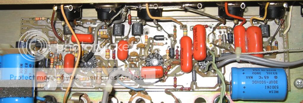
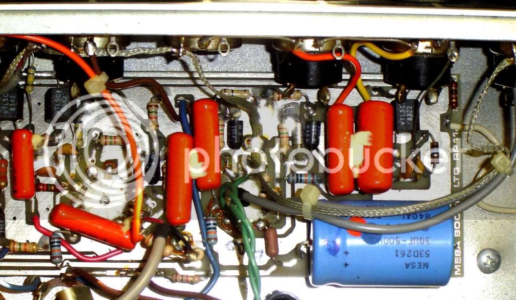
This is a bit of an extension on a previous post asking about what happens when a IIC gets modded up to a IIC+. Well, I'm not sure what they do at Mesa for that mod, but I'm currently in the process of mapping out the guts of my IIC prior to it getting modded. This new thread that I'm starting is really only for those who are interested in the details of the circuitry...sorry to everyone else who might be bored.

Even though I'm early in my investigation, I've already found one really odd difference in the IIC circuit: the cathode resistor and cathode bypass cap on V1B are bizarre values...Rk = 15 kOhm and Rc = 0.1uF. According to on-line schematics and traditional values from other amps, these values ought to be more like Rk=1.5 kOhm and Rc = 15 uF or larger (or completely absent). I've got a little video tour here...

http://www.youtube.com/watch?v=iuqTwjYvnC4

Does anyone have a clue why boogie did this? Does anyone have a IIC that they can check to see if they have the same value? Does the IIC+ have this value?

Based on a reverse-engineered IIC+ schematic done by the guys at SLOClone, I don't think that the IIC+ uses these values. That schematic shows more traditional values. When MikeB at Boogie does his upgrade to the IIC+, will he swap out these components?

Does anyone have any thoughts as to why they did it this way?

Chip
 
Thanks for the pointer. I'll shoot him a note.

If anyone was interested in some more details on the different versions of the IIC, I found this older thread (below) and attached a little more info (and pictures!) regarding my particular IIC. There's so much variation from amp-to-amp. It seems like it was a fast changing time at Mesa.

http://forum.grailtone.com/viewtopic.php?f=3&t=12847&start=15

My new additions are on page 2.

Thanks for your interest and your comments.

Chip
 
I don't think the 15K cathode cap is an error. I also don't see why anyone would waste the money to use a .1uf 400V cap for the cathode instead of a .10 cent tantalum.
In reasoning, it's a coupling cap for the V2A. Probe for it for continuity to the V2A grid. On the later RP11A you can follow the trace right to the grid. On the RP10 it may be one of the bottom traces as it terminates to a single pad.

IIC.jpg


The IIC+ has a 1K5/15uf.

IICplusv1.jpg
 
Hi,

I agree that it looks and sounds stupid to use a high voltage cap in this location. Yup, it makes a lot more sense to use a cheaper low voltage cap. But, I checked it again. My 0.1u cap really does appear to be coming off the cathode of V1B and then goes off to the effects loop as shown in my schematic.

To compare with your pics, here is the pic of the relevant area of my circuit board.

http://picasaweb.google.com/lh/photo/0GcgxCrnqWW2VLaQDvVoIQ?feat=directlink

Note that its quite different then either of the two pictures that you showed. Also, why are your two pictures different (like the blue wire running vertically down the center of your second pic)? Is it two different amps? Has one been modified?

So, like I said, I probed it out and I think that this area of my schematic is right. I'm definitely interested in continued criticism.

Schematic V1.2: http://picasaweb.google.com/lh/photo/yGt6WAvfw7LsCc0Nk1DQUw?feat=directlink

Chip
 
Oh yeah, I did as you suggested and probed for continuity between my big 0.1u cap and the grid of V2A...

From the top leg of the cap (ie, the cathode of V1B), I measured about 240K. From the bottom leg of the cap (ie, where it heads off to the effects send), I measured about 270K.

Both of these values are consistent with my schematic if you travel from the probe point down to ground and then back up to the grid of V2A via the near-by 300K resistor. Take the resistance of that path in parallel with the direct path through the 1M resistor and you get the two values I report above.

Chip
 
The top photo is a IIC, the bottom is a IIC+. Neither have modifications.
The point of the the first photo is it is the next version of the IIC on the RP11 PCB.
It's the same circuit as yours, but it may show you the layout in ways you cannot see on your RP10.
 
The top photo is the IIC? Sweet! It's cool to see the RP11A for the IIC.

Right away, it looks like it has no Graphic EQ...the top left portion of the PCB is unpopulated and there's no EQ slider board blocking the view in the top left.

Also, does it have reverb? It looks like it has most of the PCB components, but I'm not sure that I see the wiring going off board to the reverb pot.

There's really quite a few differences in how they laid it out here on the RP11A. This is really interesting. Thanks!

Chip
 
The RP11A with four 12AX7's would be the PCB for amps with reverb. The SP11A with three 12AX7's would be the board for amps without reverb, but both are designed for the EQ to be added if ordered. If ordered with the EQ, Mesa would populate the power supply, switching LDR, fader board and preamp board. At the moment, I'm looking for some pictures I had of and RP10 upgraded to a C+ circuit. I had them five years ago, I'm just trying to find them.
 
Back
Top