New .22+ Studio owner with technical questions...

The Boogie Board

Help Support The Boogie Board:

This site may earn a commission from merchant affiliate links, including eBay, Amazon, and others.
Yet another update: I replaced the filter caps (as well as C10 and a few resistors that were out of spec,) and I convinced myself that the LDRs might be the source of my switching issue, so I swapped them out also. If anyone needs this info in the future, LDR4 is the only 21L884 or VTL5C4, the others three are 21L883 or VTL5C1 (the part numbers on the stacked pair at 1 & 2 are impossible to read while they're in place.)

At any rate, I switched it on and read 21v at C9 again, and the behavior is exactly the same, grrr!!! I did get a huge improvement in the bass response, I think I can thank the new filter caps for that.

I picked up the parts to do the lead drive mod, but I want to get this problem fixed first. I noticed that I already have a hole waiting for the pot, drilled and plugged at the factory I assume. Don, did you modify your amp yet, and if so, how do you like it?

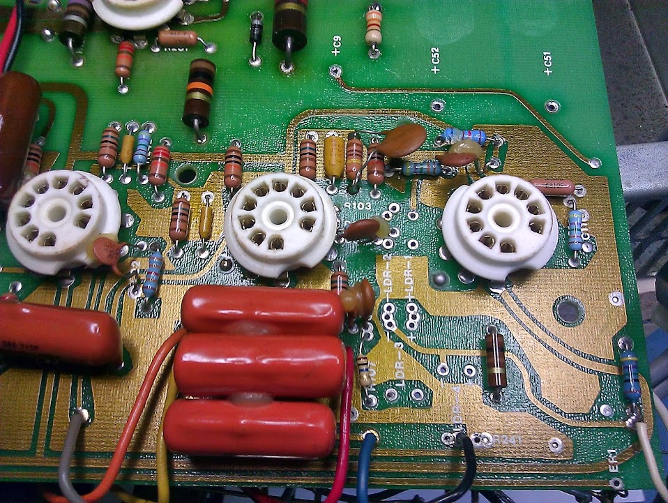
Random mid-repair gut shot:

IMG_20131020_110406.jpg
 
I recommend installing a full size reverb tank. I did, and it makes a big difference.
 
tonejam said:
I recommend installing a full size reverb tank. I did, and it makes a big difference.

Yes, that's on the list also, but mine doesn't sound too bad. It doesn't compare well to the reverb in a Fender that I own, but it's passable.
 
I did the Lead Drive mod this weekend and I love it! The amp is incomplete without it (for my use). I can turn it down to the level that I can get Marshall like tones similar to AC/DC and the Cult with a Telecaster and crank it up to Boogie levels when I want it. I installed the Lead Drive pot where the Reverb pot was and moved the Reverb pot to the EQ. footswitch jack hole on the rear of the amp (my amp does not have a graphic EQ).

I experimented with a full sized reverb tank and did not see a huge improvement over the stock tank. I think I prefer a small made in USA Accutronics tank over a new full sized imported one.

Unfortunately, I forgot to take pics as I had promised. Sorry! I'd be happy to go back inside and take any pics that might be helpful (without pulling the PCB back out).
 
That's good to know, I think that modification would be useful to me too, the level jump between channels is annoying. I'm a bit intimidated about cutting the trace, there's not much room to work in there, very little room for error. Did you use a razor knife or rotary tool for that?

No need for pics, I just wanted to confirm that I identified all the electrolytics before I ordered the replacements, thanks anyhow.
 
I cut the trace with a knife. I actually cut it in two spots about 1mm away from each other then removed the material in between to create a gap. A Dremel would've been easier. I used a Mesa pot and knob and shielded cable though I don't know if it was necessary.
 
Yet another update - I found that the "blu" output on the PT is giving me 75v rather than 50v (or 60v... crappy PDF schematic resolution..) My theory du jour is that this is the source of the switching trouble. The R1 & R2 outputs are very close to spec, and the filament outputs are right on the money.

Am I stuck with investing in a new transformer, or have I just lucked into a convenient power source for the cooling fan this amp always needed? :)
 
Hmm... I don't have the schematic on this computer. I suppose that 50 (or 60) volts on the schematic is with a load. With less than the load it was designed for the voltage would read higher. If nothing else is wrong you might be able to knock it down with zeners.
 
I'm no expert, but you haven't said anything about it, so I assume you've already fixed that solder bridge in your second photo?

What a nice change, to see the old vs the new cleaned up guts. Nice work! I only do simple mods, and I have to stare at the schematic for a few days to make very minor repairs, but I know bad and good solder work when I see it.

Kudos to you! These are great amps when taken care of! You won't regret it!
 
Don said:
Hmm... I don't have the schematic on this computer. I suppose that 50 (or 60) volts on the schematic is with a load. With less than the load it was designed for the voltage would read higher. If nothing else is wrong you might be able to knock it down with zeners.

That's probably true, though the figure I'm reading barely changes whether at idle or under load. I don't recall the exact number, but the current on that tap was somewhere around 25ma. Thanks for the zener suggestion Don, it's beyond my experience level to work out a reliable way to do it, but good to know that there may be a solution that doesn't involve replacing the tran$former.

As for anything else being wrong, there doesn't appear to be, but I haven't done any measurements off the tubes apart from the heaters. I might get into it again this weekend.
 
soundchaser59 said:
I'm no expert, but you haven't said anything about it, so I assume you've already fixed that solder bridge in your second photo?

What a nice change, to see the old vs the new cleaned up guts. Nice work! I only do simple mods, and I have to stare at the schematic for a few days to make very minor repairs, but I know bad and good solder work when I see it.

Kudos to you! These are great amps when taken care of! You won't regret it!

Thank you! The solder bridge wasn't as bad as it looked, the brown stuff was just flux rather than scorched PCB. Why they used so much solder is beyond me, underneath it all is the leg of one of the two resistors that are tied together, there's more than enough conductor there. I cleaned it up so it looks a little neater, that's about it.

For what it's worth, I've been staring at these schematics for weeks :)
 

Latest posts

Back
Top