Mesa MarkV / Saturation 'mod'

The Boogie Board

Help Support The Boogie Board:

This site may earn a commission from merchant affiliate links, including eBay, Amazon, and others.
Don’t delete the post. It is great info.

I have a theory on Bandit’s love/hate with the Mark V. I’m an engineer also, like Bandit. The Mark V is just a joy from an engineering point of view. So many options, so thoughtfully designed, it truly is an engineering masterpiece. (and a service techs nightmare, haha) My theory as to why Bandit just can’t part with the Mark V is that it is just too much of an engineering marvel. Deep down, in the heart of an engineer, there is a deep appreciation of what the Mark V accomplishes. The variety of tones, the quality of the tones (at least the one I have), the utter beastliness of channel 3, the classic crunch, punk and thick juicey tones in channel 2, and the pristine sparkle and clean of channel 1. The fact that it does not 100% live up to expectations (is it a lemon? does it just not sound like the ideal tone?) is a disappointment, but ****, it is an extremely well engineered piece of gear. Hard to get rid of it.

As for me.. I found I prefer the JAN AT7 in V4 (in V6 it seemed to reduce the gian too much). I haven’t looked back and I’m not interested in any more mods. Yes, the TC-50 and Rectoverb 25 are enjoyed very much, also. But, the Mark V always gives the biggest goose bumps (even bigger now with the vertical 2x12 Rectifier cab).
 
Please do not delete the post Bandit. You are not responsible for anyone else or their mishaps. Nothing you have stated is dangerous/unsafe or destructive. People have been modding their amps since day one. And you and everyone else here sharing their knowledge and ideas is priceless in my opinion.

These new ideas have definitely spurred my imagination, I too am an engineer and have always had a curious mind taking things to bits to see how they work since I was a small child.

Funny anecdote; I once at age 7 ish decided I wanted to turbo charge my bed bugs game. For those who don't know what that is it is a small plastic toy ( about 12 inches big) bed with a battery powered ( about 3volt or so) motor and cam underneath that made a cardboard mattress vibrate, the object being to try to catch all these little plastic bugs that would bounce about on it. I decided it would be cool to bypass the battery compartment and wire the motor direct to the 240volt wall socket! Luckily for me (and I still don't know why, I was sure I wired it up correctly) literally nothing happened so I returned it to stock and then it worked again. Obviously the AC current from the wall socket wouldn't run the motor but how nothing blow up or caught fire or electrocuted me I guess I'll never know.

Anyhoo, these mods have spurred that fire in me again as I knew they would. But, and it's a big but, trust that I will not try it if I'm not confident in my ability to carry them out properly, I may have Essex amp repairs ( top top guys by the way) do it if I feel it's too tight for my level of soldering ability. Or I may leave it as is, haven't decided yet. Curiosity is addictive though haha.

We must all carry on sharing our thoughts and knowledge, it's how we all grow.

Thanks guys.
 
I would take the mods with a grain of salt. It is just a minor improvement to the overall tone. I did install all stock tubes and was not impressed. :cry: Sounded very much the same as it did (should have run the Vertical 212 cab but did not). The 12AT7 in V4 seems to be the fix since it keeps the gain of that stage similar to the other triode circuits. With the 12AX7 in V4, there is too much gain at the higher frequency range which does seem to contribute to some brittleness (I believe it is also the first NPN transistor that is also aiding the odd harmonic overtones. There is no bypass around the GEQ as the signal chain will always pass though the transistor network with it on or off. Thinking of what is next on my list. Will need to borrow the scope to see what is going on there. My assumptions for the odd harmonic source could be the transistor network.

What I did find though, with the 12AT7 and the additional mod I was on par with the JP-2C running the combo though the vertical 212. So I had an immediate side by side comparison. Still the Mark V is not the exactly the same which is fine with me. Perhaps it is closer to what I would expect a Mark amp to sound like. Definitely a far cry better than what it was before I even had been aware of this thread. So how does one get that magic mojo that can be found with the JP-2C or the IIC+, easy but comes with a price tag. Just buy one and be done with it.

When you look at the limited schematic the Mark V is not all that impressive. Sure there is more going on with the relay logic used for channel switching and voice selection along with a few simple JFETS. The amp is not that complex in reality but tight in its layout. Much of the components used to create the strobe mute and channel changes is on the main board. That definately adds to the complexity in appearance. that must have been a fun project to work on. I would hate to assemble the preamp board as it quite stuffed.
 
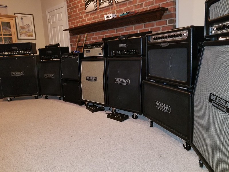
Considering my amp collection, the amps that I like the most have one thing in common. They all have class A/B power amps. The one I favor the least is the only one that has a Simul-Class power amp which is the Mark V. Interesting. Still the Mark V does have its merits plus a 10W cathode biased class A mode. It is interesting how that is all accomplished. Sure what is there not to admire in the design. Newer amps that emerged since 2016 generally do not require a change in preamp tubes to satisfy the tone junkies but some people are never satisfied so to no end they will roll until they loose interest. The Roadster can use a preamp tube upgrade to keep it out of the mud and the same would apply to the Royal Atlantic. Mark V, well depends on year it was made. Still have an issue to get past the power tube singing at reduced volume I hear the tubes vibrating at certain low frequencies it is annoying. Considering the other two amps that I have owned with Simul-Class power (MKIII and MKIV) they too have had that symptom. Perhaps it is related to the extended Class A function which is probably harder on tubes than the typical Class A/B format. Sure I have killed many pairs of tubes in the Mark III but that was due to heavy use, never replaced a tube it he Mark IV until I got the Mark V. I have had more failures with the V than any other amp I have ever owned. So my bias towards the Mark V in general can be in favor or dislike at any given moment. That love/hate thing. At times it sounds great and other times it is not very rewarding. Probably reason to why I have more amps than I need. I put all of the amps in a row in one room. Perhaps I have gone a bit too far.

25762149807_e1b2cb1f76_c.jpg
 
bandit2013 please don’t delete post! My warranty runs out in August and I’m very keen to do this mod.
 
Not sure what the mod will do for you.... I did notice a difference but now getting used to it, hard to tell what that difference really is. I may unsolder the one jumper on V6A and see how much of a difference there is to verify it is not perceived difference simply because a simple mod was made. You know, you think it sounds different because something was done.

I did the GEQ trick last because I could not find the parts on the PCB. That was not much of a change since IIC+ mode has the series resistor on V6A in use but MKIV shorts it out. Extreme voice also has the series resistor in the circuit. That basically separates the three voices.

I am thinking on what happens with Extreme mode. It appears RMY9 only does one thing, shorts out a 0.001 cap for IIC+ and IV but keeps it in the circuit for Extreme. I could not find any other reference for that relay. Me thinks to pull the 0.001 cap and tie it into the presence control so it is always there. This is not a suggestion but a thought. I much prefer the dynamics of the extreme voice on CH3 and wonder what would happened with reduced feedback in the IV and IIC+ modes. My hunch is this would nail the JP-2C since the closest voice on my Mark V is Extreme. If I do something I will chime in on it.
 
Just been taking a sneaky smoke break at work and was pondering over the Mark V and iiC+ schematics...

There's a 15uf cap (C2) on the cathode of V1a that's switched in and out by a Jfet (J175A). On the iiC+ that cap is switched too and labelled "bass shift", I'm assuming that's switched in for iV and Extreme modes and out for iiC+ mode. Unless of course it's for the ch1 and 2 voicing. Just thought I'd mention it. Would be great if there was a switching matrix schematic available hey!
 
Having a complete set of schematics would be ideal. Unfortunately I have no clue what modes that cap is used. I did write some notes on the printed Mark V schematics. For some reason I have Mark IV=2.2uF in that part of the schematic. Also the IIC+ has a 15uF cap instead of a 2.2uF cap on the 5Va cathode (what would be equivalent to this position anyways). For location on the IIC+ it would be V3B, on the Mark III it would be V3A (both have the 15uF cap) and the Mark IV is also V3A but has a 2.2uF. Increasing the capacitance value is not very difficult if you can fit the cap in there, just solder it into place in parallel to what is there already. A 10uF cap would do the trick. I did check Digikey and they are available in the molded form, 50V rated axial leaded variety. It is almost tempting to get a few caps to experiment with. Tantalum capacitor would be more desired than the aluminum electrolytic type. Making a change to the bypass cap on V5A would definitely increase the bottom end. Tempting..... I would personally leave V4 as is (except C39 delete). I was even thinking about adding some components to V2B and create another gain stage and place it between the gain tap and the V2A circuit. My OCD is having issues with that unused triode but that may be best left alone.
 
Yeah v2b is tempting to get involved I know :twisted: think that might be a bit overkill in the gain stakes though?

I wonder... if J175A was removed and a simple single pole switch wired in its place you could manually select the original "bass shift" feature of the iiC+?

Shame that the eq coupling cap and v6a's cathode bypass caps are not switched by Jfets rather than relays, it would be fairly easy then to swap them out for single pole switches and then you'd be able to manually select pretty much all the same features as the originals pull pot options and you could also select the eq or non eq coupling cap that Doug west likes! Best of all worlds! Don't imagine this would be so easy with the relays used. Unless you could isolate all the individual power supplies to them which seems to me to be probably not worth the headache. Also probably redundant with your previously mentioned mods. I am curious about the possibility of adding "bass shift" to iiC+ mode though. Maybe that along with your last two mods and C39 would be more than enough anyway. Hmmmmmmm, the mind boggles.
 
Would be quite a thing to add 'Pull Deep' from the III too..... different effect, utterly sublime when used well.
Adds weight by the tonne. Would make the V inclusive of the III beyond the similar three channel format usage..
But for now certain settings with Extreme fill that role..
 
Well I have not removed the jumper yet and probably will not. Extreme voice is incredible now with the mod. Mark IV is also more deserving of its name. Actually both seem to be comparable to the JP-2C more than the IIC+ voice but the mode does make it more ideal. MkIV is almost like the CH3 of the JP with the gain control pulled out.
 
How do we do this jumper mod? I understand that it sounds fuller, but does it also help with gain?
 
Thinking further about the cathode of v1a, making the bypass caps manually switchable could really help beef up Edge and Crunch on ch2 as well. Could be an interesting added bonus of any mod done here however wouldn't be independent of changing channels which could be a problem if the effect is good on ch3 but not so good on ch2.. Looking through the schematic there's a hell of a lot of switching going on with ch2 so it shouldn't really change the character of the ch2 modes too much I wouldn't have thought. Its essentially just increasing the gain of v1a, which come to think of it would effect every mode on every channel. Hmmmm, again if only the switching matrix was available and could be modded a manual switch could be exchanged for a channel specific tweak to the switching circuit.
 
Angle Loss said:
How do we do this jumper mod? I understand that it sounds fuller, but does it also help with gain?

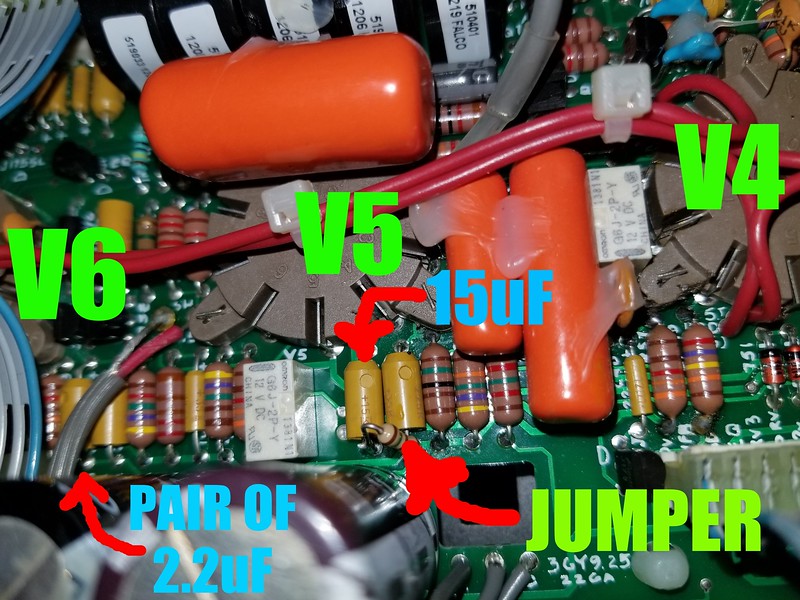
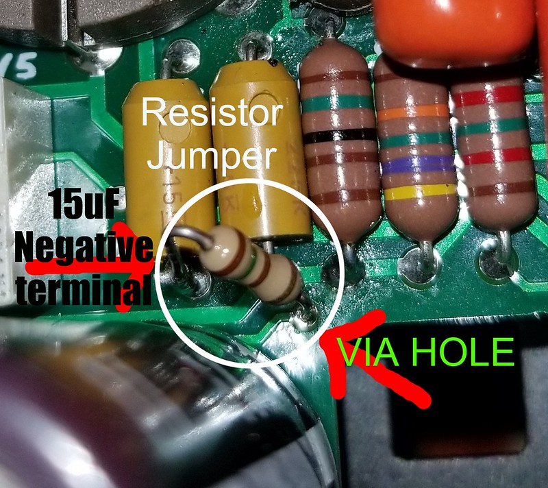
Most of the drive comes from the V5A->V4B pair of triodes. This basically sets the stage for the distortion level but V6A also plays a role in how the amp responds to the toggle switch voice. In IIC+ and Extreme voice settings the 6VA triode circuit has a 3.3k grid stopper resistor in the circuit. When MKIV is turned on, the RMY8 relay shorts this resistor which forces 6VA to get overdriven and at the same time alters the circuit input impedance. MkIV has more compression than the other two voices. This voice only uses the 15uF cathode bypass capacitor and the same would be true for the Extreme mode. IIC+ voice decouples the 15uF cap and switches over to a pair of 2.2uF in parallel (resulting in 4.4uF total capacitance) thus reducing the gain on 6VA. This circuit is also non-linear so a reduction in gain with the 4.4uF cathode bypass cap vs the 15uF bypass cap will not only reduce the effective distortion level but will also hinder the lower frequency gain. With a jumper connecting the two circuits together (ties the negative terminals of the 2.2uF pair and the 15uF cap will null the IIC+ relay terminals and the effective overall cathode capacitance will be much higher at 19.4uF vs 15uF or 4.4uF. This in effect will increase the gain of the 6VA circuit. I purposely used a 150 ohm resistor vs a wire jumper to reduce the overall effect of the total capacitance by limiting the current through the 15uF or 4.4uF depending on IIC+ or other was switched in based on the toggle switch position.
The following images will provide a location and some other details. Any mods you do to your amp is at your own risk. If you are not familiar or experienced in working on products that have the potential for holding stored energy that may be considered lethal, DO NOT ATTEMPT THIS OR ANY OTHER MODIFICATION. THIS WILL VOID YOUR WARRANTY. IT COULD ALSO VOID YOUR LIFE IF YOU NEVER WORKED ON THIS TYPE OF EQUIPMENT AND DO NOT TAKE PROPER PRECAUTIONS.

40859057261_e4b9675902_c.jpg


39049149740_48b370e9fe_c.jpg
 
bandit, thanks so much for that post. I really appreciate the thorough explanation of both what is happening in the circuit and what the effect of it is. This really sounds like a mod I'd like, so I'm going to try to do it this weekend. I already have the C39 mod and I changed out the regular V30s to Mesa V30s in my cab.
 
When doing this mod, do not let the body of the resistor or jumper to touch the large Electrolytic capacitor body. That is made of metal (sure it has a shrink wrap cover but is not suitable as an insulator) and may be connected to a different potential (more than likely it is ground). Still, you need to avoid the pitfall of creating a ground loop. If it touches during the installation no big deal. Nothing will explode or anything. Once installed, lean the jumper away from the cap and towards the tube socket. Do not it sound only be touching at the solder connections. Also, the lead going into the via hole should not be very long. Insert less than 1/8 inch into the via. Before you do this, confirm that the via connects to the two 2.2uF caps as shown in the one picture. Also, check continuity on the + side of the cap you are to solder too. The 15uF and 2.2uF caps will have the same connection on the + terminal (side of the yellow tantalum cap that has the beveled edge on it, also it is closer to the preamp tube sockets, the other side is the - terminal. The jumper (or resistor jumper) will only be connecting the negative leads of the 2.2uF caps and the 15uF cap. This is the connection on the RMY7 relay that is used to voice the IIC+ mode. Normally open terminal connects to the negative terminals of the 2.2uF caps, the normally closed terminal connects to the 15uF cap. The common terminal on the relay connects to circuit ground. The jumper basically connects the two caps together so it makes no difference when the relay is on or off. You will still have a different voice between the IIC+ and the IV setting so it does not render one mode obsolete.
 
I've had some trouble. My resistors kept bending and finally the trace lifted and no longer reaches the hole. Not sure how still do this. Any ideas?

Just for others, this mod is very difficult because of the small size of the hole and the location. I've rebuilt vintage amps and modded quite a few amps, but I am not a professional. The risk was mine to take :) No regrets other than my lack of fine soldering skills. Just a warning (as bandit warned also).

edit:

I took a look a schematic online and reread bandit's post. I decided to jumper the caps on the negative side so that it would be 19.4uF. Everything sounds fuller and it seems like it has a little more gain. The 2c+ setting is actually usable for me now. Leads (along with the C39 mod) sound fuller and more liquidy. I like it.
 
Yeah, the hole is small. Some resistor leads may be thicker. If it does not fit do not force it. I think I used a 1/4W resistor for that mod. You can use an insulated jumper wire to make the connection from the pair of 2.2uF to the one 15uF cap.

Quality of the solder iron also matters. It should not require any pressure to solder the components. Damage to the PCB trace should not happen unless the solder tip is incorrect or the temperature is too high. I would not recommend using solder irons that can be bought at wall mart, lowes, home depot, radio shack, etc.... Jumper wire from one cap to the other on the negative side should work just fine.

Sorry to hear you lifted the trace. ouch. If you need to restore to orignal, you may need to remove the board to gain access to the back side to solder a lead in place and repair or fix the lifted trace on the other side. Take a picture and post it so others can see what may happen. I am assuming that you accidentally removed the ring around the hole on the board. Lead size of the resistor may have been too large, or too much heat and pressure was used. I am not trying to critique your soldering. That trace connects the top side to the bottom side to complete the IIC+ circuit. Perhaps I should remove my mod and use a jumper wire and retake pictures so others do not fall into that trap.

I have been hand building surface mount boards for over 20 years. Some very dense and some not so bad. I also have to make mods, cut traces and such to modify a design during the prototyping phase so this sort of work is easy for me. Working on circuit boards can be tricky. Soldering wires to a speaker would be a skill level of 3 (considering the thermal mass that needs to be overcome to make a good solder connection), Soldering a pickup in place is about the same. But when it comes to mods like this, it is not something you should do if you have limted soldering experience. I would rate that at a level 7 due to the nature of the device being worked on. Most of what I do in development of new products would require a skill level of 10 assueming that is as high as the rating goes. I am just using a number to base the difficulty as there is no actual rating system used that I know of.
 
Back
Top