Mark III - undo my mod

The Boogie Board

Help Support The Boogie Board:

This site may earn a commission from merchant affiliate links, including eBay, Amazon, and others.

jaykay73

Member
Joined
Aug 18, 2013
Messages
11
Reaction score
0
Greetings,
Bought a used red stripe, want to do the R2 mod but previous owner has made a few changes.
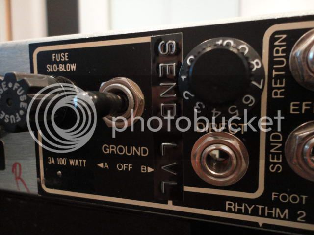
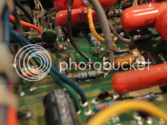
The direct out vol knob has been converted to a loop send vol knob with a wire connected to R131 and the wires to the direct out jack have been disconnected completely.
I need to have the direct out jack & knob back and then will do the R2 mod.
Can somebody kindly post the schematics for the direct out circuit.
I know a wire should run from the presence pot to the direct out level pot...
Is there meant to be a resistor on this wire? Value?
Then wire runs from the pot to the direct out jack... Is there meant to be another resistor across the jack? Value?
From reading the direct out pot should be 10K - is this correct?
Many thanks.
J
 
Thanks,
Will post pics tomorrow when I get home. I have not read about this "loop send vol mod" before. Not sure if this was done at the factory.
I'll be running my mk iii into my wet rack so I'd prefer to use a direct out which will be post-EQ.
Also planning to move the front footswitch jack to the rear to share the EQ/reverb jack - I can remove the reverb switch as I never use.
Lastly would like to move the input jack to the rear as well - mine is rackmounted, would be neater to have all the cables out of sight. Have seen pics of this done, seems very easy.
Thanks very much for the offer to call in - perhaps I may make a trip north over the summer.
Cheers,
J
 
Lid came off easily to reveal the goods inside...

At some stage the direct out knob was converted to a send level knob...

Image01_zpsaa829adf.jpg


A grey wire was soldered to R131 and the shield of this wire to the right of the adjacent capacitor...

Image02_zps462cf256.jpg


These wires were attached across the direct out pot - unsure if this is the original pot...

Image03_zpsfb9a836d.jpg


The wires previously attached to the direct out jack have been removed...

Image04_zps311af605.jpg


The unshielded wire which usually runs from the presence pot to the direct out pot has been removed...

Image05_zps28a9ed85.jpg


The R131 on my amp is double stacked - is this the norm on a red stripe?...

Image06_zpsf25dd5e8.jpg


I want to revert my direct out vol knob and socket to factory default - would appreciate if anyone can give me a schematic for wiring and resistors for this little circuit.

Many thanks,
J
 
After more reading I think this is what I need to do...

1. Insert wire from presence pot to direct out pot.
2. Direct out pot value is 10K - Linear or log ??? Probably doesn't matter too much.
3. Insert wire from direct out pot to direct out jack.
4. Wire a resistor across the jack - this looks like a 4.7K.
5. Wire the other side of the jack to ground.

Can anyone confirm if this appears correct?

Many thanks,
J
 
Any assistance here??

I found a gut shot of a purple stripe to display the direct out wiring...

Image07_zps1a361d94.jpg


Can anyone tell me the value of the resistor across the direct out pot to the direct out socket beneath??? Once I know this I can be on my way.

Thanks,
J
 
Well,

After six weeks of searching, reading and PLAYING I think I have worked out what this "send level" knob really does. It acts as a PRE phase inverter master volume control. What I have been doing is turning the R2 volume and gain near 10 and also the master volume near 10. I start with the send level on zero and slowly work it up to get a comfortable volume in the bedroom. There is heaps more gain at the speaker but without blowing my head off. With this method I can get maximum gain out of the preamp but not overload the phase inverter tube. I can also have better fine tuning of the master volume.

I'm probably going to leave this mod in, then build a line out box to capture the speaker output to send to the wet effects. After reading, this seems to be way devices such as the "suck knob" and other loop attenuators work.

Has anyone seen such a mod on a mark model before?

J
 
So-called "suck knobs" and "loop attenuators" are totally redundant and a rip-off, because these controls perform *EXACTLY* the same function as the normal, factory Master Volume. They allow you to crank the pre-amp, and lower the signal going to the power tubes.
A real attenuator is a large resistor inserted in the signal path between the *AMP SPEAKER OUTPUT* and the *SPEAKER ITSELF*. This resistor absorbs the energy going to the speaker, and gets quite warm as a result.
Anything else is nothing more than a potentiometer, in a box, in the effects loop.
 
Thanks MrMark,

I know what a real attenuator is - I build custom attenuators as a side project.
Your comments about loop attenuators are valid ONLY if the amp's master volume knob is in the circuit BEFORE the phase inverter tube - then the pot in the loop will be doing exactly the same.
However, if the MV control is POST phase inverter tube this is a completely different thing.
Can you tell me where in the Mark III circuit the MV control is placed - then we can discuss further. I suspect it is POST phase inverter tube.
I know for certain the loop return is placed just before the phase inverter tube so the pot in the loop must also be.
I'd also love for you to have a look at my photos and tell me why whoever modded my amp placed the pot in the circuit across R130.

Thanks again for your reply and I look forward to further discussion. I'd like to have a deeper understanding of the fine details of the Mark III circuit.

Cheers,

J
 
quick reply on the run..
MV is at end of preamp before signal goes to either the GEQ or V5.
Equally, presence is before V5.
Only thing after V5 is the class A/Simul switch, and the direct out level.

Have U got a schematic for the III ??
It'll show U the FX look is between V2A and V2B.
Good luck, Dave
 
Thanks Dave,
Which tube is the phase inverter?
i.e. is the MV control before or after the phase inverter?

J
 
Back
Top