Want Pre500 tone? Here's how to get it!

The Boogie Board

Help Support The Boogie Board:

This site may earn a commission from merchant affiliate links, including eBay, Amazon, and others.
Third Age Amps said:
Just changed the GAIN pot on my Two-Channel to the 1M and WHAT A DIFFERENCE! Same as what has been posted before. I doubt you would notice much of a tonal difference on a recording, but in the room it has become concussive. Not flabby, mushy bass overwhelming the other tones, just much more movement of the speakers. And that is a MAJOR factor in improving recorded tone. Speaker excursion contributes to the richness and warmth of your tone more than you would think.

Read Slipperman's ramblings and you'll learn a TON about recording distorted guitars.

It's all here:

http://www.badmuckingfastard.com/sound/slipperman.html

Anyway, Three cheers for TheMagicEight's hard work at deciphering a great tone mod!

:mrgreen:

+1 on the recording link!

I take it you changed the cap at C55 as well? Or was that change part of your "thunk mod" ?
The change is pretty awesome, I still get surprised by the tone every time I plug in :mrgreen:
 
JCDenton6 said:
Third Age Amps said:
Just changed the GAIN pot on my Two-Channel to the 1M and WHAT A DIFFERENCE! Same as what has been posted before. I doubt you would notice much of a tonal difference on a recording, but in the room it has become concussive. Not flabby, mushy bass overwhelming the other tones, just much more movement of the speakers. And that is a MAJOR factor in improving recorded tone. Speaker excursion contributes to the richness and warmth of your tone more than you would think.

Read Slipperman's ramblings and you'll learn a TON about recording distorted guitars.

It's all here:

http://www.badmuckingfastard.com/sound/slipperman.html

Anyway, Three cheers for TheMagicEight's hard work at deciphering a great tone mod!

:mrgreen:

+1 on the recording link!

I take it you changed the cap at C55 as well? Or was that change part of your "thunk mod" ?
The change is pretty awesome, I still get surprised by the tone every time I plug in :mrgreen:
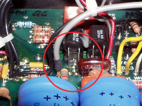
Glad you guys are enjoying it! Being my obsessive self, I've been messing with the circuit quite a bit. If you are ever bored and want to try something that (I think) is a pretty jaw dropping change, try lifting C12. Totally opens up the high end! The cap seems to define the Rectifier voice a bit, so you may prefer it the other way, but I think it's definitely worth trying out. I guess I'd compare the change to a boosted Framus Cobra, but with the Rectifier voicing.
 
10nf/450v or 5nf/450 as mentioned in previous posts? looking to do this mod today as i too would like a less scooped sound
 
Ok i cant find the d power rail can anyone help? Also i purchased a 1meg push/pull pot from boogie for a markIII and was wonderin if i could run a resister or something so that IN is normal and OUT is the mod? As you can probably tell I'm not a technician so any help would be awesome. :)
 
TheMagicEight said:
Glad you guys are enjoying it! Being my obsessive self, I've been messing with the circuit quite a bit. If you are ever bored and want to try something that (I think) is a pretty jaw dropping change, try lifting C12. Totally opens up the high end! The cap seems to define the Rectifier voice a bit, so you may prefer it the other way, but I think it's definitely worth trying out. I guess I'd compare the change to a boosted Framus Cobra, but with the Rectifier voicing.

Hmm... interesting. Have you recorded any clips of the changes since you lifted C12? I might try this but I don't want to mess up my current tone :mrgreen:
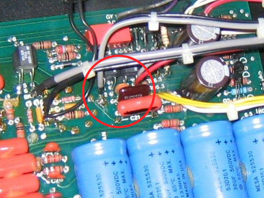
 
That cap (C12) was mainly put there to help with oscillation and noise issues, so if you can lift it, crank it and it still sounds great, enjoy!
 
Third Age Amps said:
That cap (C12) was mainly put there to help with oscillation and noise issues, so if you can lift it, crank it and it still sounds great, enjoy!

Be careful with this, just because you can't hear the oscillation does not mean it is not happening. I pretty sure that high frequency self oscillation is not good for the amp's components, especially with the gain levels of a Recto preamp design.

The only way to know for sure is to throw the amp on a scope.

My $0.02

Dom
 
domct203 said:
Third Age Amps said:
That cap (C12) was mainly put there to help with oscillation and noise issues, so if you can lift it, crank it and it still sounds great, enjoy!

Be careful with this, just because you can't hear the oscillation does not mean it is not happening. I pretty sure that high frequency self oscillation is not good for the amp's components, especially with the gain levels of a Recto preamp design.

The only way to know for sure is to throw the amp on a scope.

My $0.02

Dom
It definitely takes some high end off with the 1M gain pot. Seems like it does with the 250k pot, but I haven't confirmed that. Either way, I haven't had any oscillation issues (verified with a scope). If there were issues with oscillation, you'd notice it right away because your guitar would no longer be amplified. It's not good for the tubes if it does oscillate, but nothing else is harmed.
 
Elpelotero said:
On another note, I still have the Dreamweaver files for the Boogie Archives, and own the domain name. If any of you know how to create/upload websites, etc., I'm all ears. It's obvious with this thread people are still interested in the history of these amps.

I got a response from one of my friends who's an IT and had developed websites but is strapped for time he says. I'm waiting for a response from another friend who does website development for a living.
 
JCDenton6 said:
Based on TheMagicEight's last clip, this makes me think that most of what Mesa did when revising the recto is play around with that specific capacitor value and the gain/presence pot values, because that is the pre 500 tone to a T.
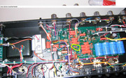
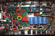
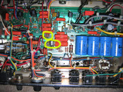
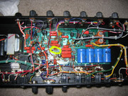
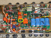
When comparing the various boards of each revision, they look identical except for this small change (addition of another resistor and position change from sideways to upwards on the PCB and the resistor next to the LDR) which happened with revision E (circled in yellow)

Revision C


Revision D


Here is where the addition of the third resistor and the positioning (from sideways to upwards) change took place.

Revision E


Revision F


Revision G


This addition of this third resistor and change of positioning (from sideways to upwards and the addition of the resistor next to the LDR) happened with Revision E.


Ok, I've got to chime in with some real knowledge here. This is not a "Pre-500" mod. This is a tone changing mod. There were a lot of changes between the Rev.C and Rev.D dual rectifiers. From the Rev.D to G boards the changes were more incremental and were intended to make the amp more stable and dependable.

The first tube of the Rev.C amps was configured completely different from every other revision. On the Rev.D and later amps LDRs were added to the cathodes of three of the four preamp stages to reduce gain. Those LDRs are not present on the Rev.C. The Rev.C had the cathodes wired up exactly like a Slo 100 and switched some resistors and tone shaping capacitors in before the first gain stage to reduce the gain and tailor the tone for a clean channel. This is one reason the clean on the pre-500's was not great. You were still running through four gain stages providing the maximum gain the circuit could provide. The Rev.Ds and on reduced the gain on three of the stages and dropped some signal between the first and second gain stages.

To create a true Pre-500 mod you would have to remove two LDRs, three resistors, and significantly re-wire the first gain stage.

These changes are not easily noticed just by looking at the PCB boards but they are there.
 
msi said:
Ok, I've got to chime in with some real knowledge here. This is not a "Pre-500" mod. This is a tone changing mod. There were a lot of changes between the Rev.C and Rev.D dual rectifiers. From the Rev.D to G boards the changes were more incremental and were intended to make the amp more stable and dependable.

The first tube of the Rev.C amps was configured completely different from every other revision. On the Rev.D and later amps LDRs were added to the cathodes of three of the four preamp stages to reduce gain. Those LDRs are not present on the Rev.C. The Rev.C had the cathodes wired up exactly like a Slo 100 and switched some resistors and tone shaping capacitors in before the first gain stage to reduce the gain and tailor the tone for a clean channel. This is one reason the clean on the pre-500's was not great. You were still running through four gain stages providing the maximum gain the circuit could provide. The Rev.Ds and on reduced the gain on three of the stages and dropped some signal between the first and second gain stages.
Huh. Thanks for your input; guess there's more to it than I had thought. The mod still sounds fantastic to my ears, but I guess it is just a mod.

To create a true Pre-500 mod you would have to remove two LDRs, three resistors, and significantly re-wire the first gain stage.

These changes are not easily noticed just by looking at the PCB boards but they are there.
Would you care to share which these are?
 
As they say: If it sounds good to you, **** 'em!

I'm not sure how the amp I had was different but I had #64 Rev C, and the clean on it was pretty good. Not as "fat" sounding as the Rev G's, but still workable.

I wish I still had that amp!
 
Msi, are you Mike B? :lol: :lol:

All joking aside, Thanks for the technical info, I'm glad you chimed in. I've been trying to get to the bottom of the rectifier revision differences for quite a while now, along with the other posters so far.
 
TheMagicEight said:
msi said:
Ok, I've got to chime in with some real knowledge here. This is not a "Pre-500" mod. This is a tone changing mod. There were a lot of changes between the Rev.C and Rev.D dual rectifiers. From the Rev.D to G boards the changes were more incremental and were intended to make the amp more stable and dependable.

The first tube of the Rev.C amps was configured completely different from every other revision. On the Rev.D and later amps LDRs were added to the cathodes of three of the four preamp stages to reduce gain. Those LDRs are not present on the Rev.C. The Rev.C had the cathodes wired up exactly like a Slo 100 and switched some resistors and tone shaping capacitors in before the first gain stage to reduce the gain and tailor the tone for a clean channel. This is one reason the clean on the pre-500's was not great. You were still running through four gain stages providing the maximum gain the circuit could provide. The Rev.Ds and on reduced the gain on three of the stages and dropped some signal between the first and second gain stages.
Huh. Thanks for your input; guess there's more to it than I had thought. The mod still sounds fantastic to my ears, but I guess it is just a mod.

To create a true Pre-500 mod you would have to remove two LDRs, three resistors, and significantly re-wire the first gain stage.

These changes are not easily noticed just by looking at the PCB boards but they are there.
Would you care to share which these are?

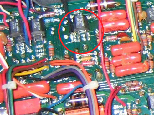
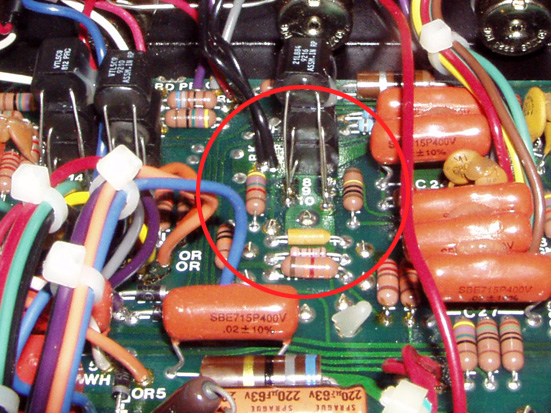
I'm sorry my reply took so long to get to you. I was looking through my pictures to see if I could find a good one of the RevC PCB board. I at one time saw a schematic of the RevC amps but I can't seem to find it again. These are the best I can give you.

The first picture is the RevC board, and it is missing LDR10 in the stack of two, and the resistor right to it's left. The second picture is my RevF rack and you can see the LDR and resistor are present.

RevC1
G8pzS.jpg


RevF1
bE5Bl.jpg


These second photos show the first tube. The differences are harder to spot. The lower LDR in the photo is different between the two photos. The RevF amp has a different type of LDR that has three leads. This LDR is a dual element and shows up as LDR3 on the schematics that are available on the net. In the RevC amp the LDR bypasses the first gain stage, in the RevF amps it alters the amount of gain in the first two gain stages of the amp. The resistor next to the grey cable is present on the RevF board and missing on the RevC board.
RevC2
plBZ3.jpg


RevF2
mUM2A.jpg


So like I said, there were some big changes between the RevC amps and the later ones, changing a single capacitor is not going to make a non-revC amp like the earlier amps. But if changing the capacitor makes the amp sound better to your ears that is what matters. I think the problem is so few people get to actually hear a rev.c amp, so we have to use words like tight and ballsy to describe the differences. Unfortunately those words can mean different things to you and me so without truly A-B'ing the two amps it's tough to say how close to the real thing your mod gets.
 
Thanks for the reply.


Quick question: This resistor next to the LDR on the V5 tube, it's not present on Rev C but it is on Rev G.
Does it impact the overall tone much? would it be best to leave in place or remove it?

 
msi, I have that schematic you're talking about. I figured it was wrong since it's missing a couple of parts and there are some weird values (presence cap is 3900pF, for example), but maybe it's more correct than I had thought. Anyone know where / how I can upload that?
 
JCDenton6 said:
Thanks for the reply.


Quick question: This resistor next to the LDR on the V5 tube, it's not present on Rev C but it is on Rev G.
Does it impact the overall tone much? would it be best to leave in place or remove it?


You don't want to remove that, it is part of the phase inverter of your amp and is essential for the power amp to work properly. Likewise changing that part is not going to change to tone. That resistor was moved from another place on the earlier amps. I don't know from where through.

They didn't just add parts between each revision, they also moved them to make room for the additional parts. It is a very tough process to get the RevG to the same specs as a RevC as I said. Until someone with a RevC wants to lend it to someone with the desire to figure out exactly where the differences are it will remain a mystery just how different they are. Looking at ****** pictures on the internet is not going to get you there.
 
TheMagicEight said:
msi, I have that schematic you're talking about. I figured it was wrong since it's missing a couple of parts and there are some weird values (presence cap is 3900pF, for example), but maybe it's more correct than I had thought. Anyone know where / how I can upload that?

If it's a paper schematic you can scan it onto a PC and save it as a jpeg, than upload it to a picture host like postimage.org (that's what I use) then post it using the 1st forum code.
Or if it's already a pic (jpeg.png...ect..) then you can just upload straight to postimage.org.
 
Back
Top