Traded a 3ch Dual Rectifier for a Mark IV, got a question

The Boogie Board

Help Support The Boogie Board:

This site may earn a commission from merchant affiliate links, including eBay, Amazon, and others.

pabloguitar

Well-known member
Joined
Mar 24, 2007
Messages
133
Reaction score
0
Location
Illinois
Just wanted to get some opinions. I've had this 3 channel Dual Rectifier for 2 years now that I never could get a sound that I liked. It's literally been in the box for about a year. I put it on craigslist and a guy emails me, wanting to trade straight up for a Mark IV. I'm thinking cool, I've had two of those in the past, and love them. Actually, I was going to add some money along with what I would have sold the DR for, and either bought a Mark IV, or waited for the 5 to come out. Anyway, we meet at a Best Buy and trade. Possibly stupid of me, but I figured that if something was wrong, I would still be ahead if I had to put in a couple hundred dollars since the DR just sat anyway. The Mark IV looked in mint condition, absolutely perfect. Got it home and checked the tubes before I even plugged it in. As soon as I took the metal cover off the V1 tube, the tube fell in my hand. I know that tubes are in pretty tight, so it couldn't have just fallen out, it had to have been out for awhile (he probably thought something was broken). I put it in, fired it up, and sweet jesus, it sounds awesome!! I noticed that the cooling fan wasn't working. Looked at the plug and it wasn't all the way in. Pushed it in the rest of the way, and worked fine. The footswitch doesn't change channels however. Fx button, and loop button work fine, but just doesn't change channels. Switch on back does change channels though, and yes, it was in the correct position for the footswitch (like I said, I've had two, so I know what the switch position should be in). Looking at the footswitch, the nut that is on the "Clean" channel is missing (maybe he had it open trying to figure it out). Might just be that that switch is sticking on for whatever reason (even thought it doesn't feel like it) and preventing a switch to either of the other two channels. So in the end, everything is perfectly fine, mint! with the exception of the footswitch possibly being a problem, although I think that it'll be fine. Any ideas about the footswitch not changing channels? Either way, I think I got an awesome deal, especially since my DR was not being used. And this guy probably thinks he got an awesome deal and ripped me off!
 
Just for the hell of it you should contact that joker and tell him you sold it for $3,000 since it was in the magic 50 serial numbers that... oh, I don't know, was the equivalent to a IIc+ "turbo" and Kirk Hammet and James Hetfield had the other two next to your serial number and were looking for that one!

Or if nothing else, call him and tell him that it wasn't broken like he KNEW it was and that you got the better end of the deal. Give him something to think about. ;-)
 
Look over the foot switch cable very carefully to make sure it hasn't been cut and that the plug on the end hasn't been yanked maybe breaking a wire or two inside. Luckily since the select switch on the amp works it indicates the problem is likely a chip inside the foot switch itself. The Loop and EQ switches are latching types and the channel switches are momentary contact which control a logic chip. This is a repair for a qualifed tech.
 
Yeah broken foot pedal leads are a classic problem.. check the lead with a muilt meter to see if there are any problems and also check the non latching switch for the channel they can stop working and just need to be cleaned out.

How old is the head?
 
Checked all wires from the plug to the footswitch for conductivity and they were all fine. Checked the switch for RHY 1 (stuck on that channel unless using the selector switch on the back of the amp) and that seemed fine too. Even sprayed it out with some contact cleaner and tried to free up anything that may be in there. After reading some posts and checking with Mesa today, one of the Quad footswitches will work on the Mark IV also. Only the FU-2A (which I have) and not the FU-2 will work on the Mark IV. Now I'm really confused... the FU-2A will not change channels on my Mark, but will activate the loop and GEQ which made me think that maybe the problem is within the amp switching system. Then I tried the FU-3 (Mark IV) switch on the Quad, and that didn't work either, which makes it seem like a footswitch problem. Any suggestions??? Anyone near Chicago on this board that has a Mark IV that I could meet up with and see if it's my amp or footswitch. I called every store around that I could think of that carries Mesa and not surprisingly, no one has a Mark IV for me to use to troubleshoot and see where my problem is.
Thanks
 
Do the LEDs on the footswitch work. In particular do the LEDs for the channels work. You are indicating that you are stuck in Rhy 1. Does that LED light on the foot switch. When you try to go to say Rhy 2 does the LED on the foot switch change but the amplifier doesn't. This could be an indication if there is a problem in the foot switch or not. If the LEDs are doing the right thing on the foot switch then the logic in the foot switch is fine. If the LEDs don't go to the proper state when you hit the channel switches this would indicate that the foot switch is not operating properly. If none of the LEDs is working it could be a power problem.

If you can describe what is happening and are at all handy with a voltmeter and can solder I may be able to help you fix this.
 
Shep, to answer your question... I'm not sure how old it is. When I called Mesa today, they said it was never registered, but shipped out in 99'. It is in the 9600 range. He claimed he is the original owner and got it a couple years ago. I'm sure it sat in a store for 6-7 years before he finally bought it, right. What an a-hole. Ok, sorry, enough of my venting... why can't people just be honest!
Blueracer, this is exactly what is happening: the selector switch on the back works fine. I checked the external switches (I only checked the channel switching ones) and they worked fine too. On the footswitch, the "EQ" and "Loop" buttons do engage the EQ and Loop like they're supposed to, and the lights work fine on the footswitch and amp. Actually these 2 switches are able to engage no matter what position the selector is in on the back, is that normal? The problem I'm having is that on the footswitch, it only shows RHY 1 light to be on and will not change to any other channel (RHY 2, Lead, or LD-EQ) either on the footswitch or amp (trying with the footswitch of course) If I try to change to another channel, it doesn't change on the footswitch or amp. Hopefully this helps explain a little better. I'm pretty good with a solder iron, and I do own a voltmeter, but not the most knowledgeable with that.
 
Ok this information helps. First that your Eq and Loop always engage no matter what the selector switch position is normal behavior. There is an exception to this but let's not muddy the water right now.

Your original idea of a stuck switch is a good one and worth checking out. The way to do this is to disconnect the foot switch from the amp and then check the continuity of the Rhy 1 switch. When the switch is pushed it should make contact and show continuity. When not pushed there should not be continuity. While you are inside the foot switch it would be worth while checking all the switches. If this is the problem the solution is to replace the switch. You can do this or send it to a tech. Mesa can supply the part. If not then we can take the next step in checking this out.

Post back what you find. We all learn from these exercises.
 
Checked the switches. Like I mentioned, I don't know that much about multi-testers, so some of this is going to sound really stupid, but I'll do my best. With the multi-tester set to ohms which is for resistance, I first verified it's functionality by touching the leads together, and the reading goes to 0 ohms, so it works fine. When the leads are not touching, the meter reads to the far left, over 1k, or it's two zero's that are connected (this is where I don't have any knowledge about it, I assume that means resistance since there is no connection). Anyway, I tested all four of the momentary switches both from the soldered back side of the circuit board, and on the switch leads themselves, and they all tested the same, no difference for RHY 1. I was really hoping that RHY 1 switch would be different and point me into the direction of a bad switch. What I am wondering about though is that when I push the switch in while testing, it shows 0 ohms which is to be expected. But prior to pushing the switch in, it shows about halfway on the scale, or at a 7, or is that 7K? It does this on each of the switches. Is this to be expected and normal, or is it indicating that somewhere a connection is made that shouldn't be?
 
First nothing you wrote sounded at all dumb and in fact you completed this test just fine. The ohms scale as you noticed is kind of backward. The zero is at the far right and the double zero is to the far left. That double zero is actually the mathematical symbol for infinity which is what an open circuit resitance is, i.e. infinite resitance. That you were mesuring some resistance, about half scale, even though the switches were not pressed is not a huge surprise as they are connected to a logic device. It is the resistance of the logic device that you were measuring. If the switches were not in the circuit and you measured them they would have had an open circuit type of measurement.

The next thing to do is to trace out the switch connections and make sure that they are hooked up properly. I am pretty sure that they are as you did measure some resistance across the switches that should be their connection to the logic device. In checking this I am just being systematic about this and eliminating possible causes of the problem. I am currently at work and don't have the schematic in front of me so this will have to wait unit I get home. This will entail some more continuity testing. So hang in there we should be able to track the problem down.
 
I checked (visually) all the solder connections on the board and they all look fine. I've seen broken solder joints before on circuit boards and that caused intermittent connections, so I'm not sure if that's what you were wanting me to look for?
 
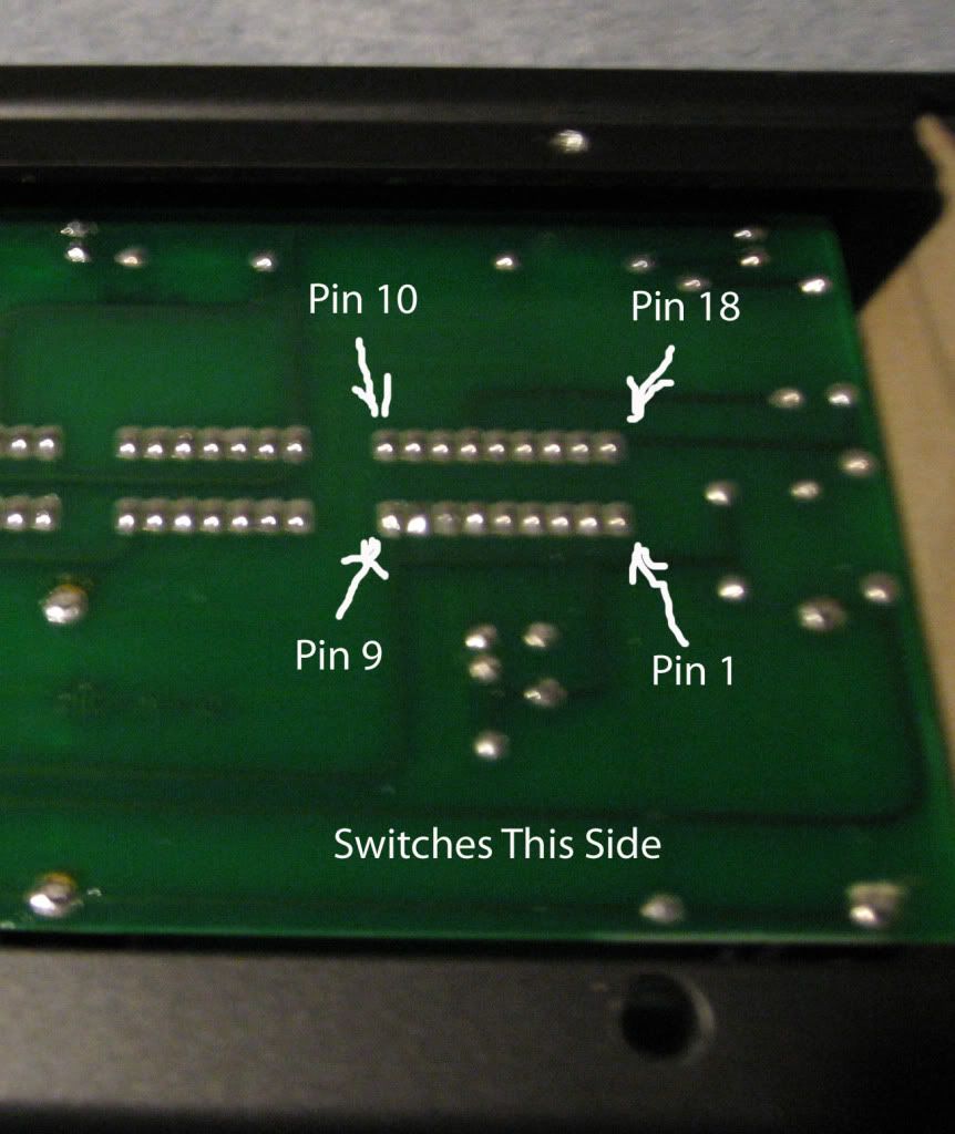
Ok the next thing you can do is check for power on the logic chip that encodes the push button switches. Refer to the image below. The IC that interfaces with the switches is labeled with pin numbers. Power is between pin 9 and 18. Measure the voltage between these two pins by placing the black probe of your meter on pin 9 and the red probe on pin 18. The foot switch will need to be connected to the amp and the amplifier will need to be on. There are no dangerous voltages in the foot switch so no worries on that. Do be careful to only connect the specific pins shown and not bridge between any. You should read about +5 volts if all is well. Post back your results. Sorry about the poor quality of the picture and graphics. I did this quick.

circuit_board.jpg
 
Yes, his, and other peoples input is exceptional! I called my best friend today and told him that he's got some competition, haha.
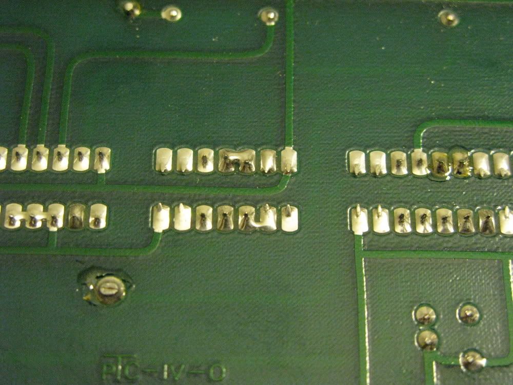
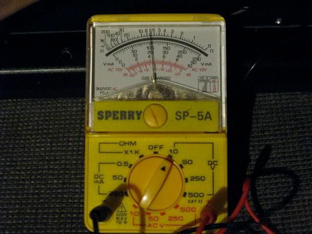
I checked the voltage between pin 9 and 18. I think I checked it anyway, this is where my multi-meter know how comes to an abrupt halt. I had it set on DC V and the selector was set on 10 (under DC V, it's possible to select 10, 50, 250, or 500). Hopefully I had it set correctly. The reading I got was about 4.5. Am I reading this correctly, I've included a picture. Also, here's a pic of my circuit board. It appears that a couple of the solder joints are touching, not on the IC that I checked, but on the one to the left.

IMG_0673.jpg


IMG_0678.jpg
 
Yes you did this absolutely correctly. The reading is dead on with mine. Ok so what we know now is that the switch encoder IC has power. Now we need to see if it is recognizing the switch inputs. To do this measure the voltage between pin 9 and 12 of the same device. Your black probe is again on pin 9 and the red probe is on pin 12. As before the amp will need to be powered up and the switch connected. With none of the channel switches pushed the reading should be zero volts. Now push any one of the channel select buttons and HOLD it in. The reading should now go to around 4.5 volts. Do this with each of the channel switches. Post your results and we will continue from there.
 
The touching solder joints are fine. These are part of the circuit design. There are three in your picture. On the device on the left it will be on pins 3, 4 and 5. On the next device to the right pins 2 and 3 as well as pins 11 and 12 are bridged. This is all fine.
 
Might have found an issue, I get a reading between pins 9 and 12 as soon as I touch the leads to them (actual reading is about 4.2) and doesn't change when I press any of the channel buttons in.
 
Yes this is a problem. It is indicating that the IC thinks that a switch is always pushed. Next thing to check is the voltage between pin 9 and pin 1. Again the amp is on, foot switch plugged in and the black probe is on pin 9 and the red probe is on pin 1. With none of the switches pushed you should have a voltage reading of about 4.5 volts. Pushing any of the switches and holding them in should send this voltage to zero. Also check the voltage between pin 9 and pin 5. This one should be about 2.5 volts. Check and post as before.
 
While you are checking these voltages also check the voltages on pins 2, 3 and 4 of the suspect IC. Black probe on pin 9 red probe on pins 2 then 3 then 4. They all should be about 4.5 volts.
 
Back
Top