Mk IIA channel switching relay buzzing, not switching

The Boogie Board

Help Support The Boogie Board:

This site may earn a commission from merchant affiliate links, including eBay, Amazon, and others.

McBarry

Well-known member
Joined
Jul 9, 2009
Messages
387
Reaction score
0
Location
Canberra, Australia
Hi, my "new" amp needed a new power cord - done.
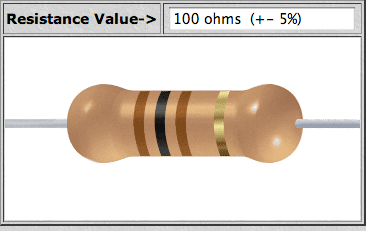
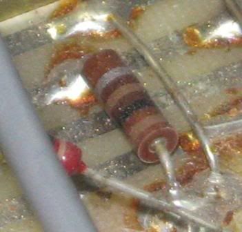
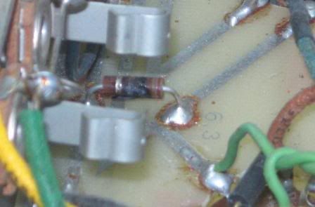
While inside I noticed a badly burnt 100ohm resistor off 6L6 pin 2. Replaced.
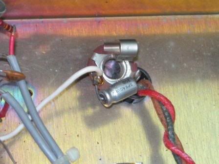
Since then the channel switching won't work and the relay is buzzing when activated.
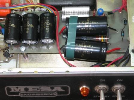
I've traced a signal to the last coupling cap before the relay (.047uf off V3B pin6 - V3A and V3B are reversed on my diagram) - after the cap the signal gets shorted to ground, as per circuit design.
Incidentally I've noticed my fist new 100ohm resistor was an old old carbon compound type, and caused more buzzing in the relay - a new 100ohm give less buzzing but still no switching..
I get good control voltages on the coil side of relay (8V - 0v footswitch side, and 8v - 5v transformer side), and it seems like it's trying to switch..

What's the collective wisdom?????
try another 100ohm??
Can the clear cover come off the relay to clean contacts?
What else comes to mind ??

thanks for any thoughts,...
Regs, Dave
 
Okay pins 2 and 7 are the filament connections on the power tubes. The 100 ohm resistor is one of a pair that should be replaced together with two very closely matched 100 ohm 1/4 watt resistors. Carbon comp is okay here. These are the filament load resistors. The other should be found between pin 7 and ground of one of the power tubes. Coincidentally the power for the relay is taken from one side of the filament supply. These 100ohms are sometimes fried during a power tube failure. check this schematic:

http://www.schematicheaven.com/boogieamps/boogie_mkii.pdf

Once you've verified both load resistors( the other could be open and not show signs of heat)and the diodes etc. of the relay supply circuit again try the switch. The relay itself can also fail and have a partially shorted coil.
 
In parallel they read 50 Ohm to ground. I you get that reading or within 5 Ohm it's probably something else.
Like RR said, they are easily fried by a catastrophic tube failure. My only issue with the design is that it's fixed, or
supposed to be fixed at 50 Ohm when the hum balance could be much less if adjusted with a pot by ear. A carbon comp to
ground should not induce any more noise than a metal or carbon film. In that circuit in my experience the 470uf/16V cap is more temperamental
than the relay, but cleaning the relay contacts would be a good start since it's moving and holding a voltage drop. If it can't hold the voltage drop
for any reason, the cap needs replacing.
 
Thx for the replies guys..
home for 10 mins then off to gig..
changed the other 100ohm resistor off the other 6L6 to identical as the other new one ( both read 99.5ohms before install)

So now I've got buzz on relay on CLEAN channel, but it actually does switch to lead channel now and hold itself there..

This thing is sent to test me I reckon..

Dave
 
Have you measured the heaters at each tube ? The hum may be from a short in the heater supply at the pins.
Maybe a cold joint so a little joint touch up may do the trick.

Power Amp- Pins 2 and 7
Preamp- Pins 4,5 and 9
 
Lots cleaning around the 2 heater tracks on both boards - hum in relay in clean mode persists.
All joints in both rails re-soldered and voltages a lot closer to equal between both sides.
After cleaning, was checking for DC actually ON the board (had this before in a Kitty Hawk 100w head), found lots of little bits ie .2, .5vdc and the odd 1.3vdc where it shouldn't be, so it needs a mega clean.
Worse is that the blue wire from V4 pin6/1 has had a previous acr-over - lots of melting on it's blue sheath and a burn mark on the board between 2 tracks directly beneath it.

Prev owner didn't disclose this, or any repair history, besides filter caps replaced.

Since my clean and before I've removed all the stray little bits of DC (through board having conductive crap on it), when switched standby ON it had an arc-over again. Same place.
Prev thought it was probably due to a 12AT7 failure, but now I'm thinking more due to crap on board and tracks shorting to each other..
Stay tuned and ideas also welcome..
Dave

ps - how do I attach images?
 
Well, when in doubt, read the manual...LOL
it mentions relay buzz being fixed by changing the supply series resistor..
Interestingly, the diagram shows a diode + 22uf cap after the relay - my board has a diode ACROSS the relay coil and no diode/cap after the relay...
I checked the 100ohm 1/2watt I removed from 6L6pin2 - it reads 196ohm... how commonly do these drift up like this over 30 odd years??
Today I've cleaned the board ++, almost no DC now anywhere, fixed a few dodgy looking connections.
My main fear is how to re-power to check voltages before repeating process with standby ON, and avoid another flash..
Am thinking all tubes out, use variac and bring up slowly, checking volts as I go?
Then repeat with V1 V2 V3 in place, no V4 as no need for it initially and maybe itwas involved in the prev arc.
Incidentally, started an initial check at full mains supply(stby "off"),to notice V4 filament quickly glowing seemingly brightly as I peered down into the chassis - might be normal but I'd have thought the glow would have come up slowly over a few seconds?? (Although the filaments aren't usually seen as they're up away out of sight in the metal caseing base).

I really need to learn how to attach pics - would make explaining a whole lot easier..
 
Flux from rosin core solder is not conductive, but some paste fluxes are and need to be seriously cleaned
with denatured alcohol or a high quality PCB cleaner. If it's arching, it's most likely going to burn the pcb
and seep further into the board. You may want to let it dry out for a few days before firing it up.
I use Würth PCB cleaner and cotton swabs.

Or:

On the V4, once you have carbon that cannot be removed you need to wire it point to point.
It should be the reverb plate supply off the reverb transformer. If you can, lift the solder tabs off the board
on pin 1 and 6 and solder the blue wire to pin 1 and run buss wire over to pin 6 to get the voltage off the board.

Also, some preamp heaters are brighter, faster or even flash when powered up.

A 100 Ohm resistor reading or drifting up to 196 Ohm is highly unlikely. Is it a 200 Ohm ?
The 100 Ohm should be brown/black/brown/gold. A 200 Ohm in that spot would surely cause
an imbalance in the heater supply and hum like mad.

For photo's, go to photobucket.com and get an account. It will allow you to get and IMG code link for sharing,
like this.

Picture6.png
 
Thx BB. here's some pics with captions.


S6300197comp.jpg

Relay. 68ohm/diode/470uf cap all visible to right, NO diode/cap on left to footswitch as shown on schematic. Diode obscured by pot is ACROSS relay coil.

IMG_4395compressed1.jpg

burnt blue 355vcd supply to V4. under are "d" 385vdc rail, and 6.3vac heater rail to V4 pin 4+5. Crazy filter cap job visible.

IMG_4396compcropped.jpg

Burnt blue 335vdc from reverb transformer to V4pin6 &1. Burn crater beetween tracks underneath. Edge track = 385vdc "D" supply, next to is 6.3vac supply to V4 pin 4&5. "D" track leads to board edge only ie supplies nothing so track was cut about 2cm back. Blue wire re-sheathed with cover.

IMG_4378compcropped.jpg

100ohm 6L6pin2, measure 196ohm when removed. The partner to the burnt one.Link wire to it's right was ALMOST down touching the track underneath. Found this >5 other places.. poor quality..

IMG_4360compcropped.jpg

Burnt 100ohm 6l6pin7. just visible it's cracked on underside. Was in 2 pieces in 2 when removed - can't see how it was anything but super-high resistance..

How would U approach startup ie variac etc?? pull tubes?
I wondering if theres another source of hum on the coil in clean mode, or if I should just change the supply resistor.. On the CRo the supply waveform is clean..
 
That cap job is scary. Oi !!! Caps have a strange way of getting your plate voltage out of whack depending on how
many Uf's you increase.

If you have 50 Ohm in parallel for the heater supply ground reference and the carbon cleaned up
a Variac would only delay the inevitable. Fire it up with pre's in and power tubes. I'm curious as
to what the plate voltage and the negative voltage is to pin 5 on the power tubes.

You may want to replace the reverb transformer. God knows how it arched and what damage it may have done.
 
Agree,and those caps are held only by their leads...hmmm..
Ordered some new F&T so will get the supply going correctly first.
Then check preamp board for any stray DC on the board after my mega-clean.
Then pull V4 and it's tranny supply and hit standby, (praying for no arcing, LOL) and voltage check everything.
If all good, play with relay 68ohm supply resistor to remove relay mechanical hum in clean mode.
Then re-connect reverb and test. Will likely disconnect it but want to ensure it's OK first.

Will post results after caps arrive.

BB, have U ever had the clear lid off one of those relays??
 
Make sure you don't have any cold joints on 2/7 and V1-5 4,5 and 9.
The two green wires for the 6.3V supply should start at the V5 (PI) and work
left to V7 and V6. From V6 is should be jumped with a twisted pair of cables to V1
pins 4,5 and 9. From V1 the trace is below the circuit board so and interruption at the pins
will hum.

I have never had the top of the relay off, but since it switches I would rule it out as having bad
contacts for now. The diode across the coil and cap at the input is to stop it from popping.

Post your negative voltage and plate voltage if you can.
 
Finally,,
caps arrived..snuck in before the volcano delays to flights.

Haven't done full voltage checking yet, but found something interesting..
Without footswitch, (so switching channels with the pull switch), relay is quiet as a mouse.

There's only a handfull of components it could possibly be.
Think I've found the 22uf electro on c/diag on f/sw side of relay - there's a tiny Sprague ON the f/sw jack from active to ground.
Not sure of it's markings and value though-
SPRAGUE +
30D
TE - 1302
3 - 50DC +
USA 7848H

50vcd seems obvious, but what about its value??
I'll whip up another f/sw with LED and if no improvement, then the cap seems the only possible leak to ground causing the relay chatter.
Once relay sorted, then I'll try amp with standby ON and hunt some voltages, esp the ones BB suggested, (stdby red supply wire will re-route under board also).
BB, also my 6.3v tracks on the preamp stay above board, (without actually pulling the board out, as it looks double-sided taped in as well as other connections.

IMG_4428comp.jpg

IMG_4422comp.jpg
 
Think it's sorted..
The footswithc LED is dropping about a volt across the relay, giving the chatter.
Raised the LED series - 680ohm to 900ohm - silent!!!!!!!!!!!!

Might try and raise bit more to drop as little voltage as possible, & so have as little current going through the relay as I'm able.
Wondering if the actual fsw is not a Boogie one - seller said it came with the amp, but I wonder if the music store threw it in, even though the schematic is identical to Boogie.
Anyone heard or seen these before??
IMG_4462comp.jpg

IMG_4463cmp.jpg

IMG_4464comp.jpg

Here's the guts with the extra 220ohm resistor I'm trialling..
 
quick update - Mesa confirmed these fsw's were supplied in the early days.

Lastly, awful relay thump - loud from clean to lead, bit louder lead back to clean.
(Obtrusive loud, not the level that you could live with, or say yeah, it's normal relay noise).
Haven't isolated yet if it's coil, or reverb side or signal side, or combination...
Can't find much info on this particular symptom - anyone have any workaround for relay thump?
Diode across relay is insitu.
My CRO isn't storage, so thump is gone before I really see what it is/was...

Have read put a 10uf cap parallel with diode, but that's about it..
Any ideas? Thx.
 
Whoever serviced this amp in the past deserves to DIE. There's no way that Mark left the factory with such poor wiring.
 
Yes, agreed about wiring..
and that cap job was just a killer...

I made an error in relay thump description - it's louder clean TO lead, and almost silent lead back to clean. Sorry..
I've hunted with CRO but it's v hard to see the pop clearly. I think it's only on signal side of relay and not reverb.
Remove V4 - no change.
Ditto V1-3.

I'm seriously frustrated as I can't easily isolate the symptom(s), AND it's a known problem which implies a design issue and hence unlikely "easy" solution.

Any/all ideas greatly appreciated..
 
Hi McBarry,
Did you ever reach a conclusion with this?
I have used a MkIIa live for years, with the 'thump', and just lived with it. The bass player always made rude comments about the thump, until I retired it in favour of a MkIIC+.
If the MkIIa didn't have the thump, I would still be using it live over the MkIIC+.
Cheers
Ian
 
Hi Ian,
trawling through old posts looking for reverb tranny failure info (I suspect my supply resistor has drifted and fried tranny primary), found this unanswered on from U.

To answer, no, I never found a solution, but did narrow the causes.
I wasn't happy with "that's the way it's designed" and wanted to diagnose and then treat.
Essentially, see last post page 1. http://forum.grailtone.com/viewtopic.php?f=3&t=53193

Bad news is there's no real cure, except stop signal (mute strings), wait half a sec, switch and blast away.
Dave
 

Latest posts

Back
Top