IIC+ Switching / Grounding Help

The Boogie Board

Help Support The Boogie Board:

This site may earn a commission from merchant affiliate links, including eBay, Amazon, and others.

Jay Omega

Well-known member
Joined
Aug 17, 2020
Messages
238
Reaction score
379
Location
USA - OH
Hello - I've been trying to convert my IIB HRG to a IIC+ by making my own preamp boards and have failed twice so far. I've ended up with a ground loop / buzz that I can't tolerate so I've stripped the amp down again.

Can anyone help me understand the grounding on the switching please? I think the 1N5352 and the 470uF 16V cap are grounded back to the PT bolt or the power supply card ground, but it looks like the 6.2V zeners / pull lead switch are grounded to the signal ground pour on the preamp board? I can't follow the preamp ground pour as it's hidden under or obscured by components in the pictures I've seen.

Any help would be greatly appreciated!
 
I take it it's a hum/buzz problem only when the lead mode is enabled?

I'm not sure "grounding" is the issue: there is no AC current flowing through the switching network: the LDR's are DC biased. The circuit works essentially like this: The 60VAC supply is half-wave rectified, and is regulated to about 13V with the 15V Zener and 470uF cap. This voltage goes to the cathode's of the LDR's through a 3.3K resistor. This 13V supply also flows through a 470ohm resistor to another Zener, this time at half the first Zener's voltage (around 6V).

When lead mode is disabled (off), you have 13V on the cathodes, and 6V on the anodes, so all of the LDR's are reverse biased, hence they are all off and the lead channel is bypassed. When you hit the lead footswitch, or pull the lead pot, the cathodes are grounded, setting the cathodes to 0V, but current for the LDR's drops across the 470ohm resistor and the 6V Zener turns off.

This current is limited to the bottom left portion of the board, and returns to the PSU board via the ground cable between the preamp board and the psu board. If you really wanted to eliminate AC bleed as a problem, you can disconnect the wire from the PSU that goes after the 1N4006 diode and 680R/3W resistor on the top corner of the PSU board, and power it directly from a 12V battery. This will provide a pure DC to the channel switching network and if you are still getting hum/buzz it can't be coming from the switching circuit(s).
 
I appreciate the time you put into the explanation, agreed with your description of how the switching circuit works and that there is no AC current present. My theory is the buzz was coming from a ground loop. If the LDR supply is connected to the chassis at the PT or via the power supply board common, and the preamp board has one ground "plane", and the preamp board is also connected to the chassis by the flat wire braid, you have a big ole ground loop and could have the pulsed DC charging currents from the switching supply traveling to the chassis thru the input jack and back to the PT.

*I think* the twisted wires that bring the 60VAC and ground to the preamp board near V4 are only used for the half-wave rectifier and the 5W zener and 470 uF cap return currents. It looks to me that the 6V zeners are tied to the main preamp board ground which is used for signal. My instinct tells me best practice would be to keep the entire switching supply (6V zeners included) separate from signal ground to avoid a ground loop, but pictures are ambiguous and that's what I'm hoping somebody can help me to verify.
 
Is it true that you only get the noise when you are in lead mode? I inferred that was the situation based on your question but I realize you never said so explicitly...
 
It's been a while since I broke it down unfortunately, but I only remember it bothering me on the lead channel. I might just build a standalone preamp similar to a Studio preamp and see if I can get that going without noise. I'm worried about rebuilding the IIB too many times as the tabs on the EQ sliders are fatiguing and Mesa won't sell me replacements.
 
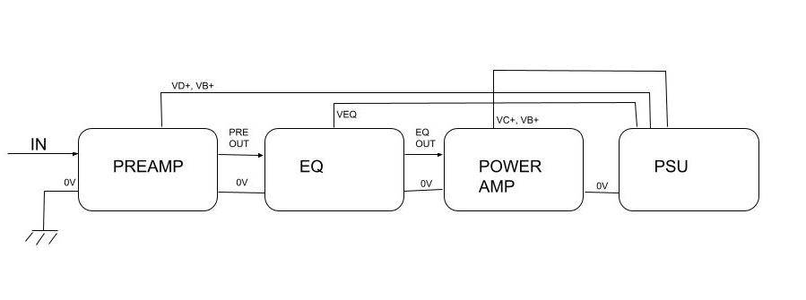
If signal follows audio 0V, then loops shouldn't be possible.

This is the ideal arrangement, with only two connections to the chassis: one, at the safety ground to the power cord, and another, to bridge analog 0V with chassis right at the input jack.

hierarchy.jpg
 
Revisiting this, hoping for some help from anybody who has worked on these or can take a peek at their amp..

The area circled in red is where the 6V zener for amps with EQ catches ground. The problem is that this should be a copper "island", because the trace coming from the 470R should hit the lead master LDR anode, and there'd be no way to extend the ground plane there. The only practical option that I can see, assuming there are no vias / jumpers hidden under the LDR, is that ground is connected to this pour underneath.

Anybody know anything about this or able to confirm by looking at their amp? I haven't been able to find any revealing pics on the internet, and it's literally driving me nuts at this point...
iicplus_swground.png
 
Revisiting this, hoping for some help from anybody who has worked on these or can take a peek at their amp..

The area circled in red is where the 6V zener for amps with EQ catches ground. The problem is that this should be a copper "island", because the trace coming from the 470R should hit the lead master LDR anode, and there'd be no way to extend the ground plane there. The only practical option that I can see, assuming there are no vias / jumpers hidden under the LDR, is that ground is connected to this pour underneath.

Anybody know anything about this or able to confirm by looking at their amp? I haven't been able to find any revealing pics on the internet, and it's literally driving me nuts at this point...View attachment 156
Just curious, is that a RP11 A board?
 
Hmmm...? That puzzles me now. My C+ has a RP11 and I looked at its preamp PCB for comparison last night ( my OCD makes me do things like that) . My board has another trace thats not in your pict. Mine has eq. I'll check again to be sure. I wish those reverb leads were out of the way. lol. But I can see enough. I'll get back. Blessings. Jim
 
Hmmm...? That puzzles me now. My C+ has a RP11 and I looked at its preamp PCB for comparison last night ( my OCD makes me do things like that) . My board has another trace thats not in your pict. Mine has eq. I'll check again to be sure. I wish those reverb leads were out of the way. lol. But I can see enough. I'll get back. Blessings. Jim
I checked again. Its the same. The picts blown up more than I thought. lol. Btw, what's that resistor for that feeds the LDR B cathodes? Thanks, Jim
 
It serves two purposes I suppose, limits current on the four lead LDRs when the lead mode is engaged, and provides adequate zener current to the 6V zener used in the switching.
 
It serves two purposes I suppose, limits current on the four lead LDRs when the lead mode is engaged, and provides adequate zener current to the 6V zener used in the switching.
Ty!. Imo, you are very savvy with amp electronics.👍 . I posted this in a new thread but you can probably answer it. On my schematic of a C +, there is a later factory mod to the effects loop send jack in which a resistor is placed that goes to return jack (muting lug). Anyone know what this would do? Does it reduce signal a bit for effects and reverb? since reverb is tapped off return jack.? If you dont have a copy of the best schematic out there for the C+, i can try to copy it here.Tia, Blessings.
 
Ty!. Imo, you are very savvy with amp electronics.👍 . I posted this in a new thread but you can probably answer it. On my schematic of a C +, there is a later factory mod to the effects loop send jack in which a resistor is placed that goes to return jack (muting lug). Anyone know what this would do? Does it reduce signal a bit for effects and reverb? since reverb is tapped off return jack.? If you dont have a copy of the best schematic out there for the C+, i can try to copy it here.Tia, Blessings.
I’d have to see what you’re looking at to say for sure, but if you put a resistor from the send jack tip to the return jack shorting, you are correct that it would attenuate the signal but it would not affect reverb or effects. The FX recovery stage sees roughly 4.7k source impedance, and develops on a 47k, so a resistor as I’ve described would add to its value to the 4.7k as they’re in series when the loop is bypassed. When the loop is used, it would be removed from the circuit and have no effect
 
Ty for your reply! Dang, I was hoping that it would attenuate my verb some cause it sounds like crap. I kinda understand what you said 🤔. . if this link works, its the most accurate one out there. I spent hours tracing it and there are a couple errors. Anyway, the effects loop shows the jacks being grounded but they are switchcraft 112's and the grounding lugs aren't used anyway. At your convenience, if applicable, look over schematic and reiterate your words of wisdom. Blessings, Jim.
 
Ty for your reply! Dang, I was hoping that it would attenuate my verb some cause it sounds like crap. I kinda understand what you said 🤔. . if this link works, its the most accurate one out there. I spent hours tracing it and there are a couple errors. Anyway, the effects loop shows the jacks being grounded but they are switchcraft 112's and the grounding lugs aren't used anyway. At your convenience, if applicable, look over schematic and reiterate your words of wisdom. Blessings, Jim.

I moved the send over by speaker outs. I temporarily put a 2.2k on end of black lead to send. The other two black leads on return, one goes to verb pot, the other connects in between 150k and 4.7k. 4.7k goes to ground. I never really had a chance to hear the effect of the added 2.2k. I was hoping that it would help my verb but you say no? Thank you for your time!!!
IMG_20220803_203948.jpg
 
Ty for your reply! Dang, I was hoping that it would attenuate my verb some cause it sounds like crap. I kinda understand what you said 🤔. . if this link works, its the most accurate one out there. I spent hours tracing it and there are a couple errors. Anyway, the effects loop shows the jacks being grounded but they are switchcraft 112's and the grounding lugs aren't used anyway. At your convenience, if applicable, look over schematic and reiterate your words of wisdom. Blessings, Jim.


As shown in the schematic, the resistor will not reduce reverb drive signal, and would likely have a minimal attenuation on FX send unless you're driving a low input impedance device.

If you'd like to reduce the reverb drive, you could increase R33 (which results in less impact to the circuit, but you are getting into less common resistor values) or decrease R34 to 180k, 150k, or lower. On an RP11, these are located above V4 on the high voltage side of the preamp card
Ty for your timely reply!! And advice! I know where these components are , I had my head inside my chassis for years! 🕵 😞 👍. If I start with the 1 meg resistor (33), could I just put another resistor in series with it to add resistance? If so, what would be a good starting value? There was this mod I found here ( actually its on the schematic) where if you wanted more swell you would lift the lead of the 220k and wrap it around the lead on the 1 meg. It wasn't clear as to what leads on each . Anyway I lifted the right side of the 220k and tacked it on the right side of 1 meg. Result was noise when verb pot was turned up. I didnt want more swell, I want less swell correct? A local tech that I've lost contact with said that we have to get your verb sounding better. I didnt ask how. I knew very little back then. I stumbled on a schematic that tucked in my amp when he replaced a preamp plate resistor. He tweaked the verb circuit on diagram by replacing the .01uf (C25) with a .005 . And he drew a .005 cap in series with the 1 meg input resistor. I wish that I would have asked him what that would have done. 🤔 In the MKIV series amps, there's a .005 instead of the .01 (C25) and a 470k instead of the 1 Meg. And a couple other changes in the MKIV verb circuit. But what's your thoughts on a starting value for resistor in series with 1Meg if you think that's wise? And thoughts on the .005 caps my local tech suggested? I apologize for the lengthy reply. I'm a learning DIY . I'm like a sponge absorbing all of the info I get. Blessings, Jim
 
Ty for your timely reply!! And advice! I know where these components are , I had my head inside my chassis for years! 🕵 😞 👍. If I start with the 1 meg resistor (33), could I just put another resistor in series with it to add resistance? If so, what would be a good starting value? There was this mod I found here ( actually its on the schematic) where if you wanted more swell you would lift the lead of the 220k and wrap it around the lead on the 1 meg. It wasn't clear as to what leads on each . Anyway I lifted the right side of the 220k and tacked it on the right side of 1 meg. Result was noise when verb pot was turned up. I didnt want more swell, I want less swell correct? A local tech that I've lost contact with said that we have to get your verb sounding better. I didnt ask how. I knew very little back then. I stumbled on a schematic that tucked in my amp when he replaced a preamp plate resistor. He tweaked the verb circuit on diagram by replacing the .01uf (C25) with a .005 . And he drew a .005 cap in series with the 1 meg input resistor. I wish that I would have asked him what that would have done. 🤔 In the MKIV series amps, there's a .005 instead of the .01 (C25) and a 470k instead of the 1 Meg. And a couple other changes in the MKIV verb circuit. But what's your thoughts on a starting value for resistor in series with 1Meg if you think that's wise? And thoughts on the .005 caps my local tech suggested? I apologize for the lengthy reply. I'm a learning DIY . I'm like a sponge absorbing all of the info I get. Blessings, Jim
The changes he made will reduce the reverb level a bit, and will cut bass. The driver stage already cuts bass as the 470n cathode bypass cap creates a shelving filter. I think it would be difficult to notice a difference after his changes.

If it were my amp, and I wanted less reverb drive and didn’t know how much, I’d remove the 220k resistor and wire a pot in its place temporarily. Then you can turn the pot until you’re happy, then remove it from the circuit and measure and replace with a resistor. I wouldn’t mess with the 1M as it connects to the incoming trace underneath the board. I think the 220k has both its connections on the topside.

If you wire a 220k in parallel with the 1M as suggested by the schematic, you’d significantly increase the drive level, hence reverb volume, and may overdrive the driver, or saturate more if it’s already breaking up.

I’ve never got along with the Boogie reverb configuration. I’m not a huge fan of spring in general though either. Boogie verb is before the loop and I tend to like reverb after effects I run in the loop. On all my boogies, I unplug the tank and leave the volume at zero
 

Latest posts

Back
Top