Hmmm one side of my Stereo 295 Poweramp has stopped working

The Boogie Board

Help Support The Boogie Board:

This site may earn a commission from merchant affiliate links, including eBay, Amazon, and others.

japster

Well-known member
Joined
Aug 3, 2010
Messages
63
Reaction score
0
Side A has decided to stop making any noise, well apart from a very quiet "ppppphhhhhhttttsssss" when I first switch it off standby.

Apart from that it's silent. All the Tubes are lit up, and at present only using it in the house so not been over working it.

It makes no difference if it's in class A or Simul-Class mode, still no sound.

Any ideas ?
 
Hey, I would check the fuses first, then tubes. If nothing there, then maybe a bad resistor or something stupid like that. One side of my 2:90 stopped working... one resistor was to blame, probably because i left the output tubes in too long. You might open it up and check the connections, and check for burned up stuff, check continuity with a multimeter... being careful not to blow yourself up discharging a capacitor. :)

scott
 
I wish I could offer some suggestions but I'm quite ignorant about the technical stuff. Please do keep us 295 owners posted on what's up. I hope it's nothing too serious.
 
Swap the 12ax7 tubes from channel B to channel A and see if the problem change channel.
 
Hmmm nope swapped all the valves from B to A in turn,

Problem stays with Channel A

Can't find any fuses or the like inside, only the one on the Front and figured it that was gone none of it would work,

Any other ideas guys ?
 
If it's not the tubes or fuses, and your cab and interconnects are fine, then it is most likely an internal circuit problem with the amp. Where are you located? a boogie tech might be the best solution. probably cost 100-120 to fix if you go that route.

scott
 
Yeah my cab and interconnects are fine cause I'm swapping everything to Channel B and it works fine.

I'm in the United Kingdom, Wales to be exact. Don't think there are any Boogie Engineers around here :)

I've checked around the Channel A circuit board and can't see anything burned out. Measured a few resistors around the Valve bases and everything seems ok when compared to Channel B values.

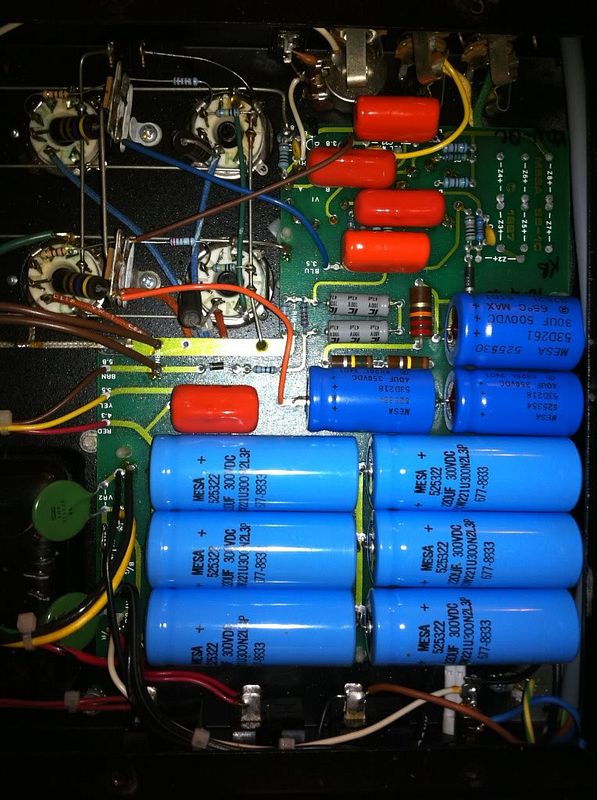
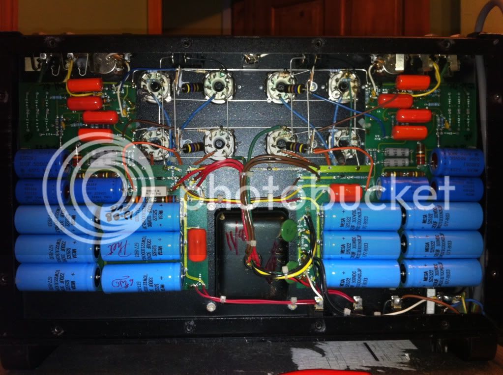
Any advice ? Please see Photo's Below

IMG_0017.jpg


IMG_0016.jpg
 
The only thing that looks suspect from the picture is the color of the top right tube socket. It's a tiny bit discolored, maybe the blue resistor that connects the pins is fried. Other than that, it looks like new.

scott
 
The screen resistor of the right-bottom socket (big carbon-one) looks different. Maybe it's not the first time it failed. I will take some voltage mesurements when the amp is on (BE VERY CAREFULL, LETHAL VOLTAGES !!!!). You should have around 500v on the plates, a bit less on the screens and 30 to 50v on the cathode (not sure about the exact value).
You can also check every solder point first to see if current can pass through.
 
Hi yes well spotted the bottom right large resistor has been replaced before I bought it. It's actually a 2.2k ohm. Not a 2.7 like the others.

It measures as 2.2k though so I don't think it's gone. I did wonder why it had been changed though.

Will take some voltage readings and let you know.
 
Still getting nowhere with this,

I want to get side A working again as a backup or to hopefully run my cab in stereo.

Any Teckies out there ? What do I need to buy to fault find this ?

Searched the net for local Mesa Engineers but nothing.

I've checked everything I can
 
Did you replace that resistor with a 2k7 ?
Also try the stereo input, it could simply be a problem with the input jack
 
Right,

I seem to have traced the fault back to the Phase Splitter section of Side A. I've kinda ruled out the Power Tube area as all the readings I'm getting are comparable to Side B which is working fine.

I'm a little confused as to why each Phase Splitter section has 2 x 12AX7's ? I'm assuming a faulty tube in either of these Phase Splitter sockets would cause no sound signal output to the Power Tubes, is this correct ?

I'm getting wierd readings on the plate voltage on these splitter tubes that are different to the healthy B Side of the amp.

Can anyone help me out here ?

Cheers,
 
Ha Ha,

I've found it !!! :mrgreen:

.1 µf Cap (Orange Drop type) between V1 output and V2 Grid in the phase splitter section, it had gone short circuit. (2nd from the top on the right side if the pics posted above)

£1.60 for a new one, bargain !

Also found quite a few Carbon 2W resistors had gone over their tolerance value so replaced them too. All for around £5.

I know the circuit quite well now if anyone gets any like problems :D
 
japster said:
Ha Ha,


I know the circuit quite well now if anyone gets any like problems :D


Hi there!

My 295 works fine. But I am getting new power supply caps for my Quad, since it wont harm anything changing them after nearly 23 years.
How difficult was it to disassemble the 295 in order to get the new resistor in place ? So I can just take of the circuit board and solder on those 12 (!!!! and even 6 other smaller ones) new 220µf 300V caps like easy peasy ? :D
 
Hi there,

Taking out the circuit boards is a bit tricky but you only have to de-solder the stiff output tube valve rails and the leads from the inputs / feedback circuit. It's then possible to ease the boards off their plastic mounts with most of the power cables still attached. This will allow you to work on the board in a somewhat vertical position while you change the caps

How much were the filter caps btw ?

Good luck
 
Cheers mate!

Yes, I looked at your pictures for finding the values for the caps.
I found Illinois Capacitors, 6,45 dimes each, i.e 4,111 quid on eBay.

also you may need 2x Sprague Atom 30uF 500V , £9/$14 each also on ebay.

But! The 4 pieces of 40uf 350v caps were harder to find... Still searching, or can I just use 40uF @ 500V as substitute ?


ek49dh.jpg
 
No pb putting 40uF/500V instead of the 350V, it's a maximum voltage rating.

Edit : just watch their size, they may be bigger.
 
Back
Top