DC-5 FX Loop Mod, Series/Parallel Switch

The Boogie Board

Help Support The Boogie Board:

This site may earn a commission from merchant affiliate links, including eBay, Amazon, and others.

Mike Boogie

Member
Joined
Dec 17, 2015
Messages
7
Reaction score
0
Hello fellow DC-5 modders,

I came up with a simple design for switching between a series or parallel FX loop. I've gathered insight from this forum in the past and thought I should reciprocate.

My design:
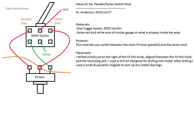
R5DOSUil.png


Wiring:
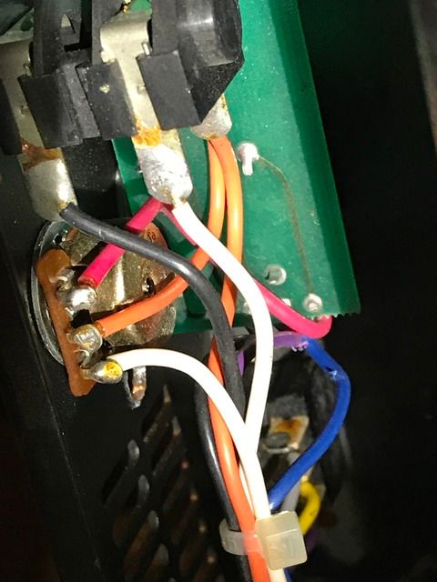
naeXnz0l.jpg


Drilled hole:
3pI8wpNl.jpg


Finished Project:
siKSEXsl.jpg


I oriented the toggle switch so that parallel is the down position, while series is the up position.

FYI: My DC-5 is the a revision.

Enjoy!
 
Awesome mod. Anyone else tried it? Mine's already been switched to serial and honestly I'm not sure I'd want parallel back but nonetheless that is one wicked mod.

I take it worked out for you? Notice any difference between the time fx when you switch back and forth?
 
I use a GT-8 (in manual mode) via the 4-cable-method, and the signal gets a bit squashed in the loop portion. Usually it doesn't bother me, but sometimes it does. It's kind of convenient to just flip a switch on the back of the amp, with the mix knob already dialed in, and then just switch to another pre-programmed patch setup for 100% wet delay.

I find it's more open with the parallel loop, but I prefer the series loop for the flexibility.
 
Hi,

Can someone here help me out with how to correctly do this mod?

I see the new switch but can't quite tell where all the wires are going.
Is this accurate???:
Red 1 - center tap of pot
Red 2 - original red line (under the tip tie) gets removed from the FX send jack and goes to this pin (leaving the original send jack to center tap still there ???
Red 3 - Goes on top of existing corner (green wire)

White 1 - Empty
White 2 - White wire right side of pot gets removed and goes here
White 3 - from new switch to right side of pot.

What I'm really unsure of is the Red 2 and where that comes from seeing that its behind everything else in the diagram.

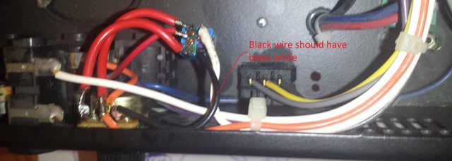
Here is my stock setup:


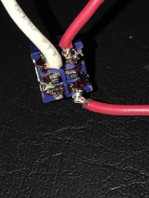
and my new switch waiting to go in..


Thanks in advance.
 
Hi,

In your photos:

1. The pre-existing red wire that is attached to the top terminal of the potentiometer, must be detached and connected to the middle-right terminal of your switch.
2. The top-right terminal of your switch must be connected via a new red wire to the top terminal of your potentiometer.
3. The bottom-right terminal of your switch must be connected via a new red wire to the middle terminal of your potentiometer.

4. The pre-existing white wire connected to the bottom terminal of your potentiometer, must be detached and connected to the middle-left terminal of your switch.
5. The top-left terminal of your switch must be connected to the bottom terminal of your potentiometer via a new white wire.

All the other wires stay as they originally were.

Please make there are absolutely no bits of metal floating around in there from the hole you drilled.
 
Thanks.

Without that I would have certainly botched more than one connection there.

A quick note to any others who happen across this thread. I tried to give myself enough internal clearance but the hole I added for the new switch was still slightly too close to the circuit-board that's in there. I was able to mount the switch so it toggles side to side but not up/down. I'd suggest getting pretty close to the grill vent openings to ensure you have the clearance.

Thanks again!
 
I’ve been looking for a mod like this for a while and stumbled across this today. I’m going to try this mod today and am really excited to get this loop in series.
 

Latest posts

Back
Top