Pentode/Triode Mod on Mark III blue stripe.

The Boogie Board

Help Support The Boogie Board:

This site may earn a commission from merchant affiliate links, including eBay, Amazon, and others.

psychodave

Well-known member
Joined
May 29, 2006
Messages
616
Reaction score
0
After reading another thread, my interests are really peaked about doing this mod since I love the pentode power on my MarK IV.

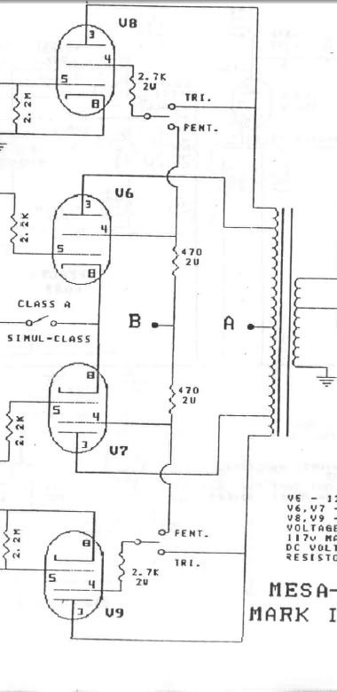
I have a Mark III blue stripe, long head with a 1/2 power switch on the front. I do not have class A switch on the back, so I thought this would be a great place to put a Pentode/Triode switch.

Can anyone comment on if my thoughts are correct? I understand that I would remove one side of the resistor across the OUTSIDE power tube socket points 4 and 5. I would run that to the switch and the other side of the switch back to the opposite pin (completing the circuit when the switch is thrown). I would do the exact same thing on BOTH outside tubes. Of course I will use a heavy duty switch. Is there any issues with this mod since my amp has the 1/2 power switch? Would I still be able to use both 6L6's and EL34's ...I know the manual says to use EL34's since they are more rugged. But I believe this mod will create more power to the tube hence my concern. I currently use Sylvania 6L6's so I know they will hold up, but in the future I may go to new production.

Any help is greatly appreciated.
 
You would want to use a DPST 15A On/Off switch with each side of the poles going from pin 3 to pin 4. Pin 5 is the bias supply. Cut the current screen grid lead to pin 3 from pin 4 and remove it. This way the switch will be the breaker from class A Triode to Class A Pentode.
 
Yup, that schmoog whet out appetites :)

What about for us Greeny owners? I understand we'd have to ADD a resistor between pins 4 and 5 and the switch simply "inserts" the resistor or not, right?

First off, is it really pins 4 and 5?

Also, is it the same pins for both the inner 6L6s as well as the outer ELs?

Finally, what value and wattage resistor should I add.

BTW, any thoughts on where to put the switches??

Edward
 
Boogiebabies said:
You would want to use a DPST 15A On/Off switch with each side of the poles going from pin 3 to pin 4. Pin 5 is the bias supply. Cut the current screen grid lead to pin 3 from pin 4 and remove it. This way the switch will be the breaker from class A Triode to Class A Pentode.

gotta use a DPDT on-on switch. I realized that its not enough to simply disconnect the resistor, it needs to be connected to the feed that the resistors for the inner tubes are connected to. I took a look at the IV schematic and this is how the switching is done there. heres the important bit of the schematic. note the switch labeled pent/tri and where its connected.

IVschem.jpg
 
and I was wrong, it is pins 3 and 4 not 4 and 5. cocaine is a hell of a drug. as for you greenies, the resistor should still be there, you are just doing the mod in reverse. so its the same procedure.
 
I was thinking as a temporary mod, just removing one side of the resistor on the outside tubes and leaving it for a few days to see if I like it….or using a hole in the back that is currently use for something else…like the DI. If I do like it, then I would drill for a new hole and locate the switch to the new spot. I don’t see why I would need a DPDT switch? A DPST would either engage the resistor or disengage the resistor…. Unless I may not be understanding that if the resistor is removed a straight connection would need to be in its place… :?:


Edit, I just re-read you post...If I understand correctly, the DPDT need to be in place so that the inner tube resistors still get fed.
 
Hey Schmoog,

Thanks for the update and clarification on the pinouts and switch! Cool. I must have misread initially, but my green strip already Has the resisitors ...excellent! So the DPDT simply switches between continutity or the resisitor, as I read it, ...sounds nice and simple. And I can do the exact same to the inner 6L6, too.

BTW, how much draw will this simple circuit draw? I am thinking of a pair of miniswitches ...will that be insufficient to handle the current load of said pins?

So what is the "feel" or "vibe" that you're trying to capture with going to the triode mode, especially with in the inner pair? Sonic description, perhaps? Thanks, man!

Edward
 
in triode mode, the tubes will begin to compress earlier, and compress more. its been describes as similar to the tonal differences between hitting a string with your fleshy thumb and hitting it with the pick. I like triode for most of the stuff I do. but if I am playing metal or really heavy rock, I like pentode better for the extra punch it gives. Triode mode is good for getting that EVH sort of too much gain sound, and can really lend a brown character to the amp.
 
Most excellent, thanks Schmoog! Now I really can't wait to try it out! :)

BTW, any thoughts (to anyone, not just the esteemed Schmoog :) ), regarding the current draw and whether miniswitches are sufficient in handling said circuit? TIA :)

Edward
 
a mini switch should be fine to handle the current flow. Radio shack actually carries a nice flatted metal mini toggle rated for 6A and 125 VAC. Just to rehash a little, remember that the switch you use should be a DPDT On-On switch. Here's the link to the radio shack part.

http://www.radioshack.com/product/i...PAD/Product+Type/DPDT&fbc=1&parentPage=family

EDIT: According to Boogiebabies, the switch would need to be 15A Rated, so I will see if I can find a 15A mini toggle....
 
How about this switch?

http://store.metroamp.com/product_info.php?cPath=22_24&products_id=455
 
psychodave said:
How about this switch?

http://store.metroamp.com/product_info.php?cPath=22_24&products_id=455

Can't see it, the site is down. but as long as it is 15A @ 125 VAC DPDT On-On it'll work fine
 
Schmoog said:
psychodave said:
How about this switch?

http://store.metroamp.com/product_info.php?cPath=22_24&products_id=455

Can't see it, the site is down. but as long as it is 15A @ 125 VAC DPDT On-On it'll work fine

just saw it. whatever switch you use needs to be DPDT On-On as its not enough to simply disconnect the resistor. It has to be connected with the 4th pin from the inner two tubes. So in the end, you are switching the end of the resistor from pin 3, to wherever pin 4 from the inner tube is soldered to.
 
Schmoog said:
Schmoog said:
psychodave said:
How about this switch?

http://store.metroamp.com/product_info.php?cPath=22_24&products_id=455

Can't see it, the site is down. but as long as it is 15A @ 125 VAC DPDT On-On it'll work fine

just saw it. whatever switch you use needs to be DPDT On-On as its not enough to simply disconnect the resistor. It has to be connected with the 4th pin from the inner two tubes. So in the end, you are switching the end of the resistor from pin 3, to wherever pin 4 from the inner tube is soldered to.

Ut oh. I ordered it yesterday. I got in my mind DPST from boogiebabies post. I guess I need to get a DPDT now. grrr :evil:
 
you can try the DPST. Mine is wired according to the mark IV diagram I posted. I give Boogiebabies a lot of respect, and he is quite knowledgable, so I am not willing to say that he is mistaken. what I would do is unsolder the resistor from pin 3, and give it a test. just keep your eyes on the power tubes and your finger on the standby switch. Or I'll tell you what, I have a friends mark III that I am giving a once over, and on saturday afternoon I can try it first before you order a different switch and spend more money if you don't have to.
 
Schmoog said:
you can try the DPST. Mine is wired according to the mark IV diagram I posted. I give Boogiebabies a lot of respect, and he is quite knowledgable, so I am not willing to say that he is mistaken. what I would do is unsolder the resistor from pin 3, and give it a test. just keep your eyes on the power tubes and your finger on the standby switch. Or I'll tell you what, I have a friends mark III that I am giving a once over, and on saturday afternoon I can try it first before you order a different switch and spend more money if you don't have to.

I should prob get a DPDT switch like the schematic says. I would rather risk a $10 switch than an awesome amp or tubes 8) .
 
I will see what happens with the resistor simply disconnected tomorrow afternoon. so hold off til tomorrow and I'll let you know what I find out
 
Schmoog said:
I will see what happens with the resistor simply disconnected tomorrow afternoon. so hold off til tomorrow and I'll let you know what I find out

Will do. 8) I appreciate your help :wink:

If its not too much trouble, can you take a few pictures?


I was doing some thinking. I wonder how hard it would be to get a 3 way switch and set it up as down being off, middle being the outside tubes and up being all 4 tubes....? I really like this option 8)
 
Schmoog said:
Boogiebabies said:
You would want to use a DPST 15A On/Off switch with each side of the poles going from pin 3 to pin 4. Pin 5 is the bias supply. Cut the current screen grid lead to pin 3 from pin 4 and remove it. This way the switch will be the breaker from class A Triode to Class A Pentode.

gotta use a DPDT on-on switch. I realized that its not enough to simply disconnect the resistor, it needs to be connected to the feed that the resistors for the inner tubes are connected to. I took a look at the IV schematic and this is how the switching is done there. heres the important bit of the schematic. note the switch labeled pent/tri and where its connected.

IVschem.jpg

You guys are scarring me! You are messing with the highest volatages found in the amp. If pins 4 (the screen grids) are not connected the tube simply won't funtion. At the worst if you get anything crossed up your output tranny is toast. Here's a little tip that can save you some big problems for those of you who really shouldn't be trying this: Put a 1amp fuse in before you power it up to see if it works. If anything is shorted or you get the transformer taps crossed etc. a .50 cent fuse is a lot easier to replace than a tranny or tube sockets and so on. Better yet get a qualified tech to do this mod for you.
 

Latest posts

Back
Top