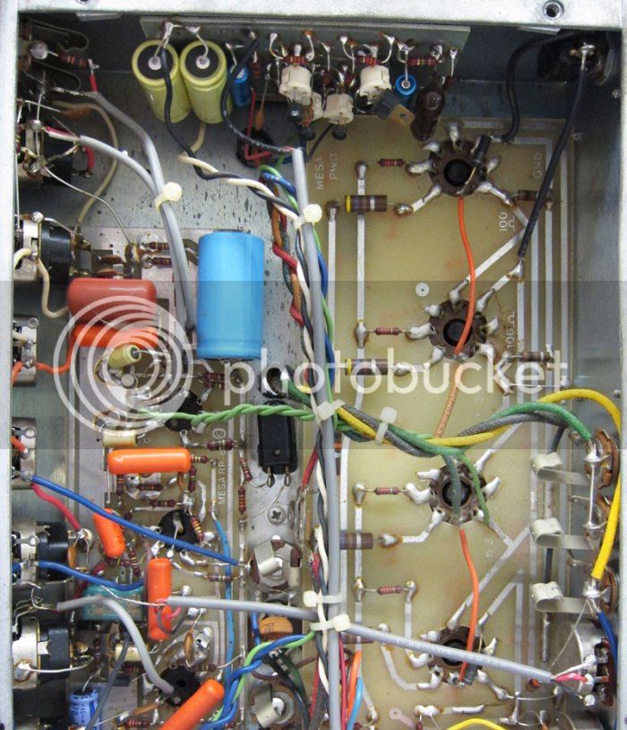
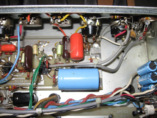
Getting this beauty back to original schematic (mk2a)

The Boogie Board

Help Support The Boogie Board:

This site may earn a commission from merchant affiliate links, including eBay, Amazon, and others.

alagami

Member
Joined
Apr 17, 2017
Messages
19
Reaction score
0
Location
Denmark
Hi there.

Since this is my first post in this glorious forum, please bear with me;).

I got my hands on a 1979 blonde mk ii a. This thing seem to be having work done on it, and i am having a hard time getting it back to its original.
Anyways, i got this problem with some of the ceramic caps. They are very microphonic. One in particular - right where i got huge noise problems ( https://www.youtube.com/watch?v=S6dCgj8c9ZM ).
So i'll try and replace it. Im struggling with the code on this thing. Please see my image. It says: "Z5U - .002M - 1KV".
My first thought was a .002 microfahrad. But via google it looks like its a .047microFahrad.
Can anyone confirm this?

I am writing a loooong article on this amp since it looks very modded and to me it looks like bad amateur work.

Here is my image (click to see. Too big for this forum):
https://dl.dropboxusercontent.com/u/109969/Musik/1979-mesa-boogie-mark-ii-b/z5u.jpg

On a sidenote. Since i noticed that there are not many images on google from the inside of a mark 2a, i have taken a lot of hi-res photos where you can zoom all the way in. So if you ever need to confirm, or just see what's inside a 2A, you can freely download my zip-files. The full-res is quite big. Hope you can make use. Its nice to have sometimes, just to confirm and such.

The links are:

web-resokution: https://dl.dropboxusercontent.com/u/109969/Musik/1979-mesa-boogie-mark-ii-b/web.zip
Full-resolution: https://dl.dropboxusercontent.com/u/109969/Musik/1979-mesa-boogie-mark-ii-b/fullsize.zip


;)Lars
 
Hi...

First off, you have a lovely early Mark IIA, not a IIB... Very nice amp. Looks like someone has changed the cathode bypass caps but otherwise the circuit looks untouched. With that said, the ceramic cap in your picture is the for the lead channel bright switch. It is a .002uf... It does look a little chewed up from someone flexing it out of the way to solder in the bypass caps. You can swap it out with another ceramic of the same value and same voltage handling. On a side note; those cathode bypass caps look a little chunky to be low value. What are they? They should be no more than 25uf. Mesa started to use the solid tantalums around this period for preamp cathode bypass so that would be a nice touch to restore back.

Nice amp!

-j
 
Hi @ lovetoboogie.

Thankyou for your reply. Are you 100% sure that it's a M-II-A? Can you perhaps tell me where it's pretty obvious when comparing the II-A and II-B?
I am trying to restore it back to it's original shape. I bought it as a II-B, so this really surprised me.

Which cathode bypass caps are you talking about? Can you perhaps point them out on this picture(if you cant see the whole image, right click and save it - then open it):
https://dl.dropboxusercontent.com/u...ark-ii-b/fullsize/mark-ii-b-fullsize-4134.jpg


lovetoboogie said:
Hi...

First off, you have a lovely early Mark IIA, not a IIB... Very nice amp. Looks like someone has changed the cathode bypass caps but otherwise the circuit looks untouched. With that said, the ceramic cap in your picture is the for the lead channel bright switch. It is a .002uf... It does look a little chewed up from someone flexing it out of the way to solder in the bypass caps. You can swap it out with another ceramic of the same value and same voltage handling. On a side note; those cathode bypass caps look a little chunky to be low value. What are they? They should be no more than 25uf. Mesa started to use the solid tantalums around this period for preamp cathode bypass so that would be a nice touch to restore back.

Nice amp!

-j
 
Going over the schematics for the mk2a, it seems this is actually a mk2a. I do not know if this is good or bad. The thing sounds fantastic, besides from the noise.
@lovetoboogie, i've been checking out those cathode bypass caps. They do look like newer ones. Does anyone know how the original looks like? Google gives me nothing;). They are coming off pin 3 from the preamp-tubes. The value are the same for both: 220uf and 35Vdc. According to the schematic (and i may be wrong since im no magician i this;)) the values should be 22/25 which i can only guess means 22uf and 25Vdc.

Is this right?

According to uncle doug from Youtube and the ampbook link, the optimal value should be around 25uf.


Hope you can help me out.
 
yes....those will need to come out. Where appropriate for a particular Mark series model, the preamp cathodes, pin 3 & 8 should get 22uf bypass cap. In the pictures you provided I count 3 of them that are incorrect. They are the blue radial electrolytics. You should replace those with something like this;

http://www.ebay.com/itm/12-Kemet-T332E226M025AS72007643-22uF-20-25V-Axial-Tantalum-Capacitors-/191549290136?hash=item2c993a3698:g:Nc0AAOSwrklVG~nm

On V1 of your amp, the input stage, you have a switchable cathode for what was called a Fetron. That would be the dead giveaway that your amp is a IIA as oppossed to a IIB. In any case, you have the correct cathode bypass cap and transistor arrangement on that cathode(Pin 3) so you can leave that.

I see you have a hum when the lead channel is engaged... lets get those preamp cathodes changed out and then we can address the noise(s)...and the reverb...

You will notice on a Mark IIA in particular the preamp cathode for V2b, pin 8, is not bypassed with a capacitor. That is correct so leave that....

I also see the electrolytic was replaced for the low voltage switching relay... Or at least it looks like it. It would be that black radial capacitor sitting behind the lead master pot. Let us know what that capacitor is and where it's terminating at...

Great pics by the way, very helpful! Welcome to Boogie-Land!

-j
 
I've just done the same test with my Mark IIB which has been recapped and the same noise is present at those levels.It seems it is inherent in these amps?
 
Got my hands on some 22uf@25Vdc today. I put them in there. Didn't change anything. Perhaps the tone and dynamics is better now. Haven't put my Strat in yet. The noise is still there.

I still suspect those old ceramic caps. If i tap on them they are very microphonic which they shouldn't be right?
Im getting a Fluke 177 this week. I am planning to measure every single cap in the preamp section. Just to make sure. If you saw my video on youtube, you'll notice the noise is on the lead-section. So i'm pretty sure that the error is in the preamp-section.
I might end up re-soldering the whole board at some point.

I checked up on Ceramic caps. Seems that noone makes those brows caps in 1KV anymore. They are blue now. Can i use these newer blue ones you think?


lovetoboogie said:
yes....those will need to come out. Where appropriate for a particular Mark series model, the preamp cathodes, pin 3 & 8 should get 22uf bypass cap. In the pictures you provided I count 3 of them that are incorrect. They are the blue radial electrolytics. You should replace those with something like this;

http://www.ebay.com/itm/12-Kemet-T332E226M025AS72007643-22uF-20-25V-Axial-Tantalum-Capacitors-/191549290136?hash=item2c993a3698:g:Nc0AAOSwrklVG~nm

On V1 of your amp, the input stage, you have a switchable cathode for what was called a Fetron. That would be the dead giveaway that your amp is a IIA as oppossed to a IIB. In any case, you have the correct cathode bypass cap and transistor arrangement on that cathode(Pin 3) so you can leave that.

I see you have a hum when the lead channel is engaged... lets get those preamp cathodes changed out and then we can address the noise(s)...and the reverb...

You will notice on a Mark IIA in particular the preamp cathode for V2b, pin 8, is not bypassed with a capacitor. That is correct so leave that....

I also see the electrolytic was replaced for the low voltage switching relay... Or at least it looks like it. It would be that black radial capacitor sitting behind the lead master pot. Let us know what that capacitor is and where it's terminating at...

Great pics by the way, very helpful! Welcome to Boogie-Land!

-j
 
Actually, i found another wrong cap. Across V1a pin 3 - should also be a 22uf, but appears to be 100uf. I wonder who the heck did this. Has he no respect;-).

another-wrong-cap.jpg


lovetoboogie said:
yes....those will need to come out. Where appropriate for a particular Mark series model, the preamp cathodes, pin 3 & 8 should get 22uf bypass cap. In the pictures you provided I count 3 of them that are incorrect. They are the blue radial electrolytics. You should replace those with something like this;

http://www.ebay.com/itm/12-Kemet-T332E226M025AS72007643-22uF-20-25V-Axial-Tantalum-Capacitors-/191549290136?hash=item2c993a3698:g:Nc0AAOSwrklVG~nm

On V1 of your amp, the input stage, you have a switchable cathode for what was called a Fetron. That would be the dead giveaway that your amp is a IIA as oppossed to a IIB. In any case, you have the correct cathode bypass cap and transistor arrangement on that cathode(Pin 3) so you can leave that.

I see you have a hum when the lead channel is engaged... lets get those preamp cathodes changed out and then we can address the noise(s)...and the reverb...

You will notice on a Mark IIA in particular the preamp cathode for V2b, pin 8, is not bypassed with a capacitor. That is correct so leave that....

I also see the electrolytic was replaced for the low voltage switching relay... Or at least it looks like it. It would be that black radial capacitor sitting behind the lead master pot. Let us know what that capacitor is and where it's terminating at...

Great pics by the way, very helpful! Welcome to Boogie-Land!

-j
 
you are working with a circuit that has been modified. troubleshooting includes putting the circuit back to stock as you indicated you are interested in doing. ...

the hum on the lead channel is being introduced when half of the V3 preamp tube is engaged. so you start by changing that tube to a known good 12ax7/ecc83...

after that or subsequent to, you take plate voltage measurements off of V3 pin 1 & 6 to ensure the stage is being fed, check the lead drive pot and it's switching matrix to ensure the channel switching relay is engaging both sides, check the low voltage feed to the relay to make sure that is fed and filtered,... since you have no hum on the clean/rhythm channel which shares its B+ filter cap with the lead channel, you can eliminate a bad filter cap...

if you have an audio probe and signal generator the hum can be isolated often in minutes. a DMM should get you there....

dont fixate on the ceramic caps... they are unusually durable. although noisy and some can be problematic, there are 1000's of Boogies around the world sounding amazing loaded down with ceramics... ;)

there are many NOS ceramic disc capacitors in all values and voltage handling online. they are still used today in many applications so there are current production offerings as well...a simple google search yielded this:

https://tvsandscreens.com/products/002uf-2nf-2000pf-1000v-1kv-20-ceramic-disc-capacitor-8-pieces

or this:

http://www.ebay.com/itm/20-RMC-002uF-500V-X5F-Ceramic-Disc-Capacitors-/191922147131?hash=item2caf738f3b:g:eek:FIAAOSwygJXh2Y1

A good primer for noise troubleshooting is this;

http://www.geofex.com/ampdbug/ampdebug.htm

Although not boogie-specific it covers many of the most common issues...

hope this helps!
 
MK IIB said:
I've just done the same test with my Mark IIB which has been recapped and the same noise is present at those levels.It seems it is inherent in these amps?
Here's my unmodded Mark IIB.Recently had a full recap.
Same noise present. https://www.youtube.com/watch?v=Yn4svYgHzk4&feature=youtu.be
 
Thank you for taking the time to shoot the video. Noise sounds very similar. I can accept some noise when overdriven, but to my ears this is too much. Or is this an acceptable level?


MK IIB said:
MK IIB said:
I've just done the same test with my Mark IIB which has been recapped and the same noise is present at those levels.It seems it is inherent in these amps?
Here's my unmodded Mark IIB.Recently had a full recap.
Same noise present. https://www.youtube.com/watch?v=Yn4svYgHzk4&feature=youtu.be
 
@lovetoboogie - I cannot thankyou enough for sharing your expertise and experience. I am quite good with a soldering iron and actually i am an electrician. Generally i undestand electronics. But i am a newbie in this tube-world. But i am laerning and eager to go deeper. Just ordered a Fluke 177 this morning. I am so thankful for any links that lead to wisdom on boogies and tube-tech. Also i've seen just about every Uncle-Doug and D-lab video on Youtube.

I will follow your advice and keep working on this amp. Hopefully i'll learn along the way.

lovetoboogie said:
you are working with a circuit that has been modified. troubleshooting includes putting the circuit back to stock as you indicated you are interested in doing. ...

the hum on the lead channel is being introduced when half of the V3 preamp tube is engaged. so you start by changing that tube to a known good 12ax7/ecc83...

after that or subsequent to, you take plate voltage measurements off of V3 pin 1 & 6 to ensure the stage is being fed, check the lead drive pot and it's switching matrix to ensure the channel switching relay is engaging both sides, check the low voltage feed to the relay to make sure that is fed and filtered,... since you have no hum on the clean/rhythm channel which shares its B+ filter cap with the lead channel, you can eliminate a bad filter cap...

if you have an audio probe and signal generator the hum can be isolated often in minutes. a DMM should get you there....

dont fixate on the ceramic caps... they are unusually durable. although noisy and some can be problematic, there are 1000's of Boogies around the world sounding amazing loaded down with ceramics... ;)

there are many NOS ceramic disc capacitors in all values and voltage handling online. they are still used today in many applications so there are current production offerings as well...a simple google search yielded this:

https://tvsandscreens.com/products/002uf-2nf-2000pf-1000v-1kv-20-ceramic-disc-capacitor-8-pieces

or this:

http://www.ebay.com/itm/20-RMC-002uF-500V-X5F-Ceramic-Disc-Capacitors-/191922147131?hash=item2caf738f3b:g:eek:FIAAOSwygJXh2Y1

A good primer for noise troubleshooting is this;

http://www.geofex.com/ampdbug/ampdebug.htm

Although not boogie-specific it covers many of the most common issues...

hope this helps!
 
alagami said:
Thank you for taking the time to shoot the video. Noise sounds very similar. I can accept some noise when overdriven, but to my ears this is too much. Or is this an acceptable level?


MK IIB said:
MK IIB said:
I've just done the same test with my Mark IIB which has been recapped and the same noise is present at those levels.It seems it is inherent in these amps?
Here's my unmodded Mark IIB.Recently had a full recap.
Same noise present. https://www.youtube.com/watch?v=Yn4svYgHzk4&feature=youtu.be
I've not been able to compare to another Mark II before now but I did also think this was a bit too noisy.Like you the tubes are new and this amp has had all the electrolyitcs replaced.So not sure if this is normal of there is something going on with my amp too but the circuit hasn't been changed at all on mines.
I'd be interested to see if you are able to eliminate the noise.
Here's a couple of pics of my amp.

20151029_165918.jpg
20151029_165442.jpg
 
alagami said:
@lovetoboogie - I cannot thankyou enough for sharing your expertise and experience. I am quite good with a soldering iron and actually i am an electrician. Generally i undestand electronics. But i am a newbie in this tube-world. But i am laerning and eager to go deeper. Just ordered a Fluke 177 this morning. I am so thankful for any links that lead to wisdom on boogies and tube-tech. Also i've seen just about every Uncle-Doug and D-lab video on Youtube.

I will follow your advice and keep working on this amp. Hopefully i'll learn along the way.

Absolutely my friend... I think it's great that you ended up with that amp. Let's see if we can get it from point A to point B... I have been working on Boogies for quite some time. I can share what has worked for me with troubleshooting. You start to see predictable patterns after so many repairs...

I ask again, did you swap the V3 tube to see if the hum went away? Remember, when you pull that lead drive you are calling on the relay to switch in that extra triode of the V3. So your focus is on that tube stage. On a smooth running Mark IIA, B or C, the lead drive is slightly more noisey, but it should only be a "white noise". The hum is a symptom, not the norm.

-j
 
I did swap the tube in V3. Didn't change anything. I do pay attention to what you recommend;-). So this evening i sat down with Uncle Doug (youtube) and went through all the basics. He is so good at learning. Also i got my Fluke177.
So i've been reading the plate voltages on all the preamp tubes. And either i am doing it wrong, or the voltages are totally off.

Here are my results (in Vdc. numbers in parenthes are voltages according to schematic):

V1A: 252 (144)
V1B: 233.7 (144)
V2A: 254 (258)
V2B: 394 (same as v2a?)
V3A: 259 (cannot see on schematic 50v?)
V3B: 98.7 (250)
V4A: 386.7 (356)
V4B: 386.7 (356)
V5A: 294 (cannot see, 80V on cathode?)
V5B: 285 (cannot see, 80V on cathode?)


lovetoboogie said:
alagami said:
@lovetoboogie - I cannot thankyou enough for sharing your expertise and experience. I am quite good with a soldering iron and actually i am an electrician. Generally i undestand electronics. But i am a newbie in this tube-world. But i am laerning and eager to go deeper. Just ordered a Fluke 177 this morning. I am so thankful for any links that lead to wisdom on boogies and tube-tech. Also i've seen just about every Uncle-Doug and D-lab video on Youtube.

I will follow your advice and keep working on this amp. Hopefully i'll learn along the way.

Absolutely my friend... I think it's great that you ended up with that amp. Let's see if we can get it from point A to point B... I have been working on Boogies for quite some time. I can share what has worked for me with troubleshooting. You start to see predictable patterns after so many repairs...

I ask again, did you swap the V3 tube to see if the hum went away? Remember, when you pull that lead drive you are calling on the relay to switch in that extra triode of the V3. So your focus is on that tube stage. On a smooth running Mark IIA, B or C, the lead drive is slightly more noisey, but it should only be a "white noise". The hum is a symptom, not the norm.

-j
 
those voltages are just about spot on...

v1 seems high because the schematic references voltages are shown with the fetron engaged. what you have is a 12ax7 so you are good there.

v2a is good... v2b you take your measurement off the cathode, pin 8, should be in the 260v range....

v3a(reverb recovery) and v3b(lead gain) are correct...

v4 is the reverb driver and v5 is the phase inverter. both of those readings are correct...


so with that said, your lead hum sounds 60 cycle to my ear. you could still have another preamp tube that has some capacitave coupling going on and the lead channel is picking it up. with a known good 12ax7 do some preamp tube swapping and see if the hum follows it. the other things to address are relay, ground, film cap, pot or lead-dress related....i see some modified trace work that doesnt look like original Mesa work coming out of the relay....

you will have to meticulous work your way through the schematic matching up the trace runs on the preamp board. i can only guess that whoever modified this previously was looking for a certain sound.

here are clean Mark II schematics;

http://soundup.ru/index.php?option=com_content&view=article&id=2556%3Amesa-boogie-mark-ii&catid=46%3Alibrary-scheme-ind&Itemid=78

the first and third from the top are both IIA's...

do you have signal on the lead channel even with the hum?

reverb and presence controls should be at zero(0) while you are doing the troubleshooting.
 
Thank you for your reply @lovetoboogie. I will be going through the board one step at a time. Hell i just bought an old osciloscope;).

To answer your question: Yes there is sound through the hum on the lead-channel.


lovetoboogie said:
those voltages are just about spot on...

v1 seems high because the schematic references voltages are shown with the fetron engaged. what you have is a 12ax7 so you are good there.

v2a is good... v2b you take your measurement off the cathode, pin 8, should be in the 260v range....

v3a(reverb recovery) and v3b(lead gain) are correct...

v4 is the reverb driver and v5 is the phase inverter. both of those readings are correct...


so with that said your lead hum is going to be relay, ground, pot or lead-dress related....i see some modified trace work that doesnt look like original Mesa work coming out of the relay....

you will have to meticulous work your way through the schematic matching up the trace runs on the preamp board. i can only guess that whoever modified this previously was looking for a certain sound.

here are clean Mark II schematics;

http://soundup.ru/index.php?option=com_content&view=article&id=2556%3Amesa-boogie-mark-ii&catid=46%3Alibrary-scheme-ind&Itemid=78

the first and third from the top are both IIA's...

do you have signal on the lead channel even with the hum?

reverb and presence controls should be at zero(0) while you are doing the troubleshooting.
 
Here's a fairly good birdseye view of a 79' IIA. You might find some use comparing the wire runs and circuit trace on the preamp board...


Thanks a lot for the image. I've been googling for this for days without finding anything usable.


lovetoboogie said:
Here's a fairly good birdseye view of a 79' IIA. You might find some use comparing the wire runs and circuit trace on the preamp board...


@lovetoboogie, i started going through the board, one small step at a time. I bumped into my first problem. According to schetatic, im missing a 470K resistor in parallel with the large cap in the preamp board. See my image below.
What really throws me off is that i found another image on the net that has the same resistor missing.

Have a look;)

My image:
470k-missing.jpg


And i found this online:
MarkII-Input.jpg


The question is what is right and what is wrong?
 
Back
Top