Typical voltages in Mark 1 amps.

The Boogie Board

Help Support The Boogie Board:

This site may earn a commission from merchant affiliate links, including eBay, Amazon, and others.

mark1406

Well-known member
Joined
Jul 12, 2006
Messages
152
Reaction score
30
Location
Sydney, Australia
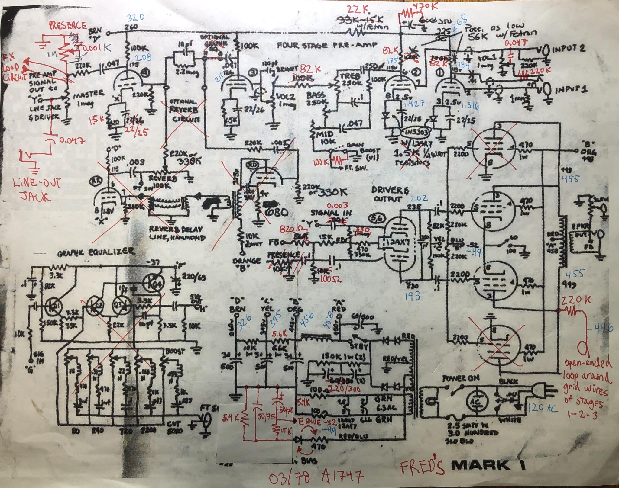
I have a Mesa Boogie SOB which I converted to a Mark 1. I’m think the rail voltages are effecting the tone of the amp.

I don’t remember what the voltages were in my original Mark 1 amp. I knew they weren’t the same as the old circuit diagram.

I will measure the voltages on the nodes of my SOB tonight and report back.

Regards

Mark
 
If I look at the early circuit diagrams, the main rail voltage is recorded as 450VDC, 446VDC, 345VDC, 260VDC, if a Fetron was used 225VDC.

I know that these voltages didn’t line up with my original Mark 1 amp.

Regards

Mark
 
Hi Mark,

Next time I have some bench time with mine I will measure, if you have not received answers by then.

Frederik
 
Much appreciated Frederik.

The voltages in the SOB MK1 are as follows.

Mains voltage: 238.5vac
O/P TXer node: 460VDC
Screen node: 458VDC
P.I. Node: 407VDC
Preamp 1 node: 361VDC
Fetron Pre 2 node: 344VDC

The amp was rebuilt, with new caps and resistors, I used the Mallory 150’s as I I had them and they sound good. The circuit is pretty much stock apart from the first triode having a 2.2uF cathode bypass cap, the Fetron voltage node has a 6.8K resistor instead of the 15K to 33K resistor, the inputs to the amp have 68K grid stoppers to keep garbage from getting into the amp, the amp has a mid boost and treble boost as well a post P.I. master volume. The main filter cap node always changed from 220>220uF to 100>100uF as the larger value can make the 50 watt amp sound stiff. They work well with 100 watt amps though.

The D.I. isn’t used and I have to get an effects loop in there to fill those holes.

98603D7A-F628-4631-A141-1759095B03BB.jpeg5E4D5DE1-6C68-4CA0-AE01-DCA48549F091.jpeg8730CB65-761E-40E8-B96D-3D29C9190E57.jpegD1A9E437-7584-4C81-A02D-717F1059AC9A.jpegA888B933-4F1C-44F3-AA73-6E8BD3EA9FCA.jpeg56A2C647-8E1E-4AEF-8AEE-E3DA8FE3B3CF.jpeg3BA2C3B2-625E-4AB8-A420-D21D89607C36.jpeg
 
Last edited:
Hello Mark,

Here are the voltages at the documented points in the schematics. I have not taken the time yet to compare with your values though, you can see my measured voltages in blue.

c5ELvvm.jpg
 
Last edited:
Thanks Fred for your assistance, I appreciate your help. I can delve inside of my amp now. The voltage to the output transformer is about the same which is promising.

Regards

Mark
 
Hello Mark,

Here are the voltages at the documented points in the schematics. I have not taken the time yet to compare with your values though, you can see my measured voltages in blue.

c5ELvvm.jpg
Hallo Frederik,
your notes (the red ones, am i right?) show an amazing detail. On the right bottom you notet a resistor going from the PA anode, attached with a wire which open end is wrapped around the grid wires of three gain stages. It would be nice, to get a picture of this. I think, it is something like a capacitive coupled (negative or positive) feedback, which affects the higher frequencies...? If you find time for a foto - thanks, Thomas
Good spotting Thomas, there are photos of Frederick’s amp on the thread titled “ Help with my 1978 Mark 1”.

Mind you I had a quick look at the pictures and couldn’t find wire wrapped around the grids of stages 1, 2, & 3. The first and second stages use co-ax cable and I couldn’t get a good look at the third stage.

Regards

Mark
 
822f721addabb01561053052026f08eb.jpg
Hi there,

Here is a picture where you see how it is wrapped, it’s the red wire around the three gray coax. I’ll see which other pictures show it from other angles. By the way here is the thread with all pictures (now that you see the wire it might be easier to spot in in the other pics.

https://boogieforum.com/threads/help-with-my-1978-mark-i.86559/
Fred
Thanks for clearing that up Fred. I didn’t think the wire would be around the co-ax cables as it would effectively be around the earth on the cables as opposed the actual grid wires themselves.

I can’t see the 220K resistor in the photos, but I don’t doubt that it’s there.

Regards

Mark
 
Hey Mark, the resistor is on the circuit board. I am on the phone now but will look at the pictures to try and find it when I’m on the computer a bit later.

Glad the pictures and schematic notes of my Mark 1 can be useful for you guys!

Fred
 
7677c5afa6ab6fce2cb0e115d270f5e0.jpg


Can see it a bit here, moslty hidden under all the wiring on the tube socket. From this angle it almost looks like the red wire is jumped with the point where the resistor ends. But that’s not how I saw it when I traced it... maybe a mistake, I might have a look tonight to confirm. Anything else you’d like to know about that mystery mojo wire? :)
 
Back
Top