Mark lll Lead Drive question

The Boogie Board

Help Support The Boogie Board:

This site may earn a commission from merchant affiliate links, including eBay, Amazon, and others.

emoshurchak

Member
Joined
Feb 3, 2007
Messages
19
Reaction score
0
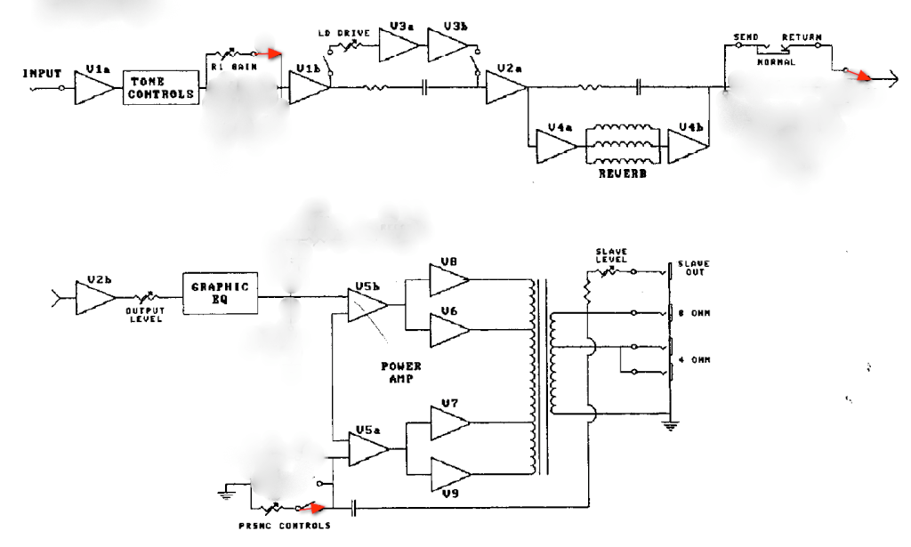
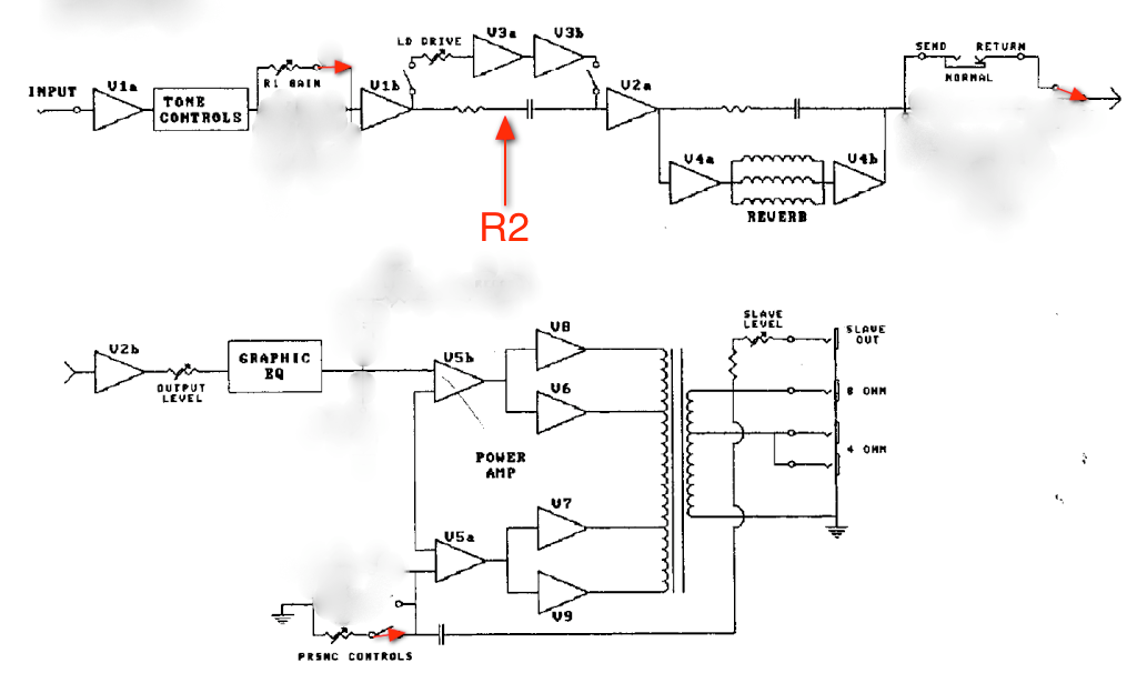
I'm trying to understand the relationship of the Volume, Master, Lead Drive, and Lead Master controls on my Mark lll. I know the Volume control is part of the pre-amp and is active in all channels including the lead channel. I think that the Lead Drive and Lead Master are pre-amp controls as well (V3). I was wondering if someone could give me a non-technical description of how the guitar signal is routed through the various circuits and in particular, how Volume and Lead Drive/Master are related.
 
Volume controls the input coming from the jack, Lead drive is the lead channel's gain knob, Lead master is just a volume control for the lead channel, and the Master is just a master volume

Volume and Lead drive are the ones that play off each other
 
Lead Master and Master play off each other as well. Whichever is set lower determines overall loudness. They are best utilized as mix controls between clean and dirty sounds to balance the relative volumes of R1 and Lead.
Running the Lead Master very low, for example, and running the Master way up to compensate will not drive the power section harder.
Unless you are using an attenuator, as in load resistor, the only way to overdrive the power section is to play LOUD. :D
 
Volume 1: Amplifies the guitar signal-First Stage of Gain and Tone Controls-Master Volume is Normal to the power amp.

Lead Drive: Takes Volume 1 setting, tone controls and adds two gain stages in series for overdrive-Master Volume is Normal-Lead Master is added here.

Lead Master: Is added to compensate for the drop in Volume from the overdrive's compression and need to keep the signal from going crazy from being clipped.

The lower the Volume 1, the lower the gain will be with the Lead engaged. The higher the Volume 1 setting, more gain will be available in Lead.
Mesa termed this Cascading Gain. One gain stage basically pushes straight through the next and increases the overdrive.

The relationship is easy. Try running your Lead mode at 8 and Adjust Volume 1 between 4,5,6,7 and 8. The gain being fed from the clean channels preamp will
push the lead channel into having more overdrive with each turn. Their are different "Sweet Spots" depending on how you run your Volume 1 or Lead Drive.

The relationship with the Master Volume is not so easy. In lead mode with lower settings like 3-4
on the Lead Master and Master Volume at 2-3 you get a bit more sizzle in the tone, but the overall volume will be close. For a fuller lead tone, run the Master Volume at
5-6 and the Lead Master at 1. The interaction with the power amp is much different. Less sizzle, more touch sensitive and the bottom and top end react in a smoother
way. This is only good if you don't play the clean channel, or for recording. If you switch from lead to clean with the Master Volume at 5, it's Über loud.

I hope this helps.
 
MrMarkIII said:
Running the Lead Master very low, for example, and running the Master way up to compensate will not drive the power section harder.
Unless you are using an attenuator, as in load resistor, the only way to overdrive the power section is to play LOUD. :D

Funny you should bring this up MrMark. This was exactly the thinking that got me trying to understand how the system works. I now realize that the only way to get power tube saturation is to crank the Master. If I do this in Class A mode, I should be able to preserve my eardrums!
 
Boogiebabies said:
Volume 1: Amplifies the guitar signal-First Stage of Gain and Tone Controls-Master Volume is Normal to the power amp.

etc...

I hope this helps.

This was exactly what I was looking for BB. I tried to get this information from the schematics but they were way above my head! Thanks a million.
 
A modified MK IVA Block diagram will also give you an idea of the signal path.


Picture3.png
 
Boogiebabies said:
... If you switch from lead to clean with the Master Volume at 5, it's Über loud.

I hope this helps.

Double that "Über". BB, thanks a lot for the clear explanation. I have been pulling some 16 to 18 hour shifts this week, starting Sunday afternoon for a 8 hour shift, after getting the tubes I wanted for the Mark III. I had only been able to put in about 10 minutes before I realized I was so tired I better do some down time. Tonight I am going back and using your information to get a better idea of how to get the tone I want. Again, thank you so much for your insight into all this. :!:

Dennis
 
Boogiebabies said:
A modified MK IVA Block diagram will also give you an idea of the signal path.

Perfect. A flowchart which I can understand. I see that the GEQ is part of the power amp as opposed to the main tone stack. I was wondering about that as well.
 
Boogiebabies said:
A modified MK IVA Block diagram will also give you an idea of the signal path...

BB. The block diagram really clarifies the signal path for me as well. Now that I can see how the effects loop is in the Mark IVA can I assume (O.K. now I may be in for trouble on many levels with that word :oops: ) that the Mark III is very similar to the signal path? I guess what I am asking is, how does the FX loop path relate to my Mark III, .50 Cal., and the Heartbreaker? Are they similar? The answer is going to let me know if I can get comfortable looping my Line6 M13 and on which amps. The only reason I ask is that my .50 Caliber hates my Boss GE-7 7 band eq. No matter what I do with the gain on the Boss in the loop of the .50 Caliber it seems to make my amp go crazy to the point of chewing up power tubes. It may just be the Boss isn't suited to the boogie. So I thought I would ask.

Thanks again.

Dennis
 
Boogiebabies said:
A modified MK IVA Block diagram will also give you an idea of the signal path.

Boogiebabies, your block diagram was a big help to me. I'm a little unsure of how the signal is split for R1 and R2. I'm guessing that there is a diversion of the R2 signal to the second gain stage (V1b) which is bypassed by the R1 signal which gets only the first gain stage (V1a). I am trying to understand the effect described by bartchamdoh in his "The secret 4th channel on a mark 3" thread. Again I'm guessing that added distortion introduced during the second gain stage of R2 is applied to the lead channel. Am I on the right track or out in left field?
 
The flow chart above is best for understanding R1 and the Lead Channel. R2 is not illustrated very well by this chart because the flow path for R2 and R1 are extremely similar. There is no obvious and dominating "side branch" like there is for the Lead Channel.

IMO, the best way to understand R2 to to think of it as R1 on steroids. Normally, one thinks of R1 as their clean channel. But, to keep it reasonably clean, some gain is thrown away at different points in the circuit. This is true in many amplifeiers that trace their lineage back to the blackface Fender amps (such as the Boogie Mark Series). When you switch from R1 to R2, much of that gain is restored. Hence, you get some distortion and grit.

Looking back at the flow chart, most of the differences between R1 and R2 have to do with that straight branch between V1B and V2A. In R1, the signal loss through that resistor is huge. When you switch into R2, some components switch in/out to make that loss much much less. As a result, V2A gets slammed with strong signal and some nice grind results.

Hope this helps.

Chip
 
Updated Block with where R2 circuit is. For R2 Mesa added another resistor and cap in parallel to these two which
are 3.3M and 20pf for the clean channel and lead input. They basically put the resistance between 0 Ohm-1M by adding a 3.3 or 4.3M
resistor and add 180pf cap for more brightness. The R2 resistance can vary from stripe to stripe due to the value of the added resistor
and cap hence, different sounding R2's.

With the decrease in resistance from R1 plus the added cap it allows much more gain to go down the signal path
and why it's still in series when lead mode is in, Hence the fourth mode of the MK III. With R2 engaged it's pushing
the clean channel harder and therefore the lead mode gets pushed as well.

In the MK IV, all these functions get switched out so you don't have them in series with the lead mode.
In the MK III, I don't think they thought about it, yet.

Hope this helps.


Picture3-1.png
 
Boogiebabies said:
Updated Block with where R2 circuit is. For R2 Mesa added another resistor and cap in parallel to these two which
are 3.3M and 20pf for the clean channel and lead input. They basically put the resistance between 0 Ohm-1M by adding a 3.3 or 4.3M
resistor and add 180pf cap for more brightness. The R2 resistance can vary from stripe to stripe due to the value of the added resistor
and cap hence, different sounding R2's.

With the decrease in resistance from R1 plus the added cap it allows much more gain to go down the signal path
and why it's still in series when lead mode is in, Hence the fourth mode of the MK III. With R2 engaged it's pushing
the clean channel harder and therefore the lead mode gets pushed as well.

That pretty much clarifies things together with Chip's response. I was expecting to see a more obvious switch for R2 that would split the path from R1. Thanks to all who responded.
 

Latest posts

Back
Top